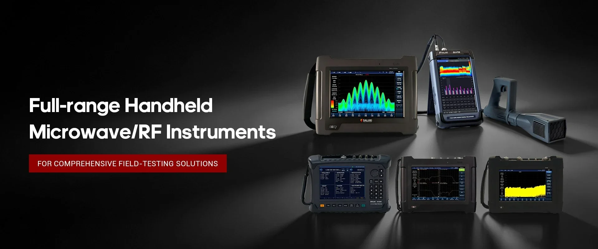
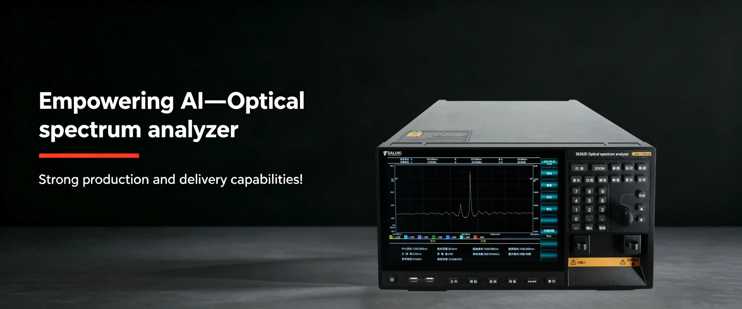
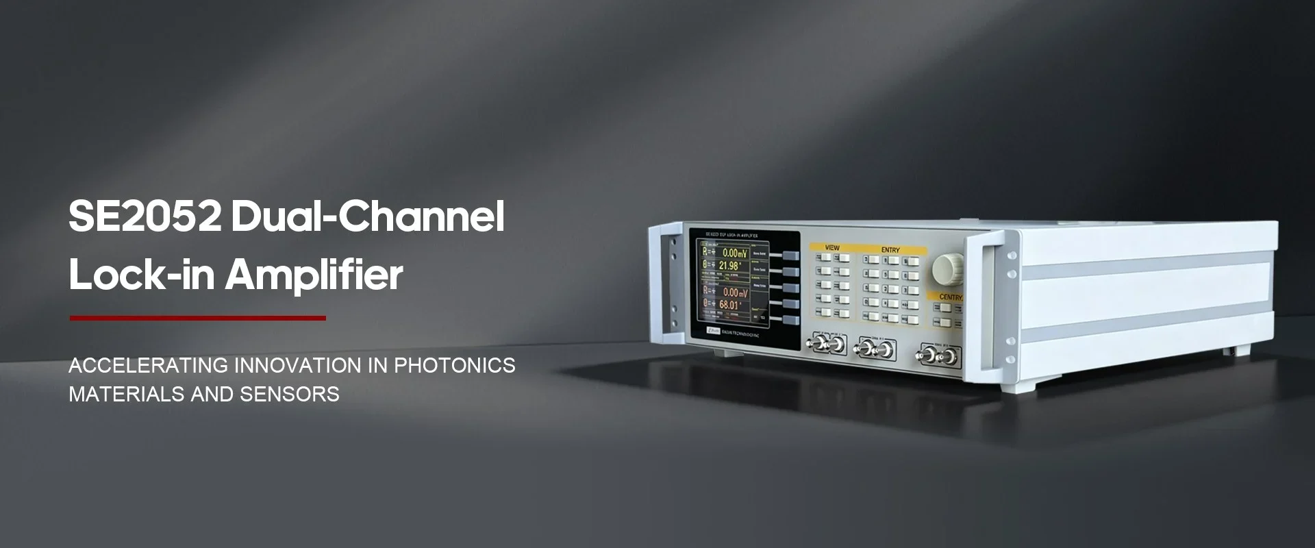
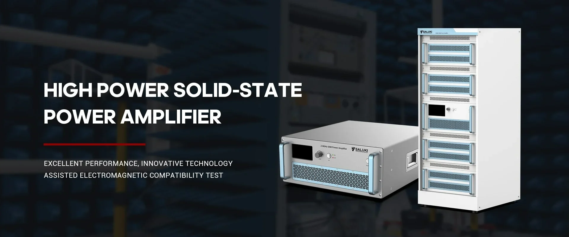
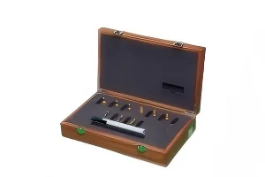
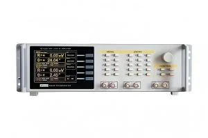
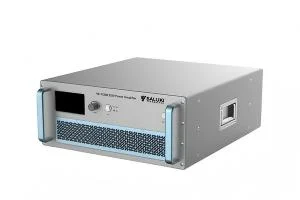
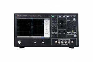
Best Selling Products
Contact us: sales@salukitec.com
As a professional RF, microwave, and millimeter-wave products manufacturer and supplier in China.
Whether you’re a reseller, distributor, solution provider, or startups, we have a solution to help you grow your business and bring new solutions to market. We believe it is a great opportunity for you to grow with us.

Company Profile
Overview
Saluki Technology Inc. is a high-tech company, supplier and manufacturer of High-end RF&MW Test Equipment, General Test Equipment, Lab Equipment and Optical Communication Equipment. Founded in 1997, the company was initially an agent of telecommunication equipment, and it once ranked second in the Chinese market. With an in-depth understanding of the market and user needs, meantime a deep accumulation of technology, the company began to develop its own brand of test equipment in 2008, and promoted it mainly for the Asian market. Beginning in 2015, the company moved its headquarters to Taiwan, and began to face more overseas markets and built the SALUKI brand.
At present, the company has exclusive agents in South Korea, Turkey, and stable partners in markets of countries like Canada, Germany, the United States, the United Kingdom, Finland, Poland, Indonesia, Israel, Vietnam, and South America.
We are committed to establishing a stable partnership with local agents to provide customers with the most professional, fast and long-term services.
Our Vision
Accurate, Fast and Reliable
-
20+
Work Experiences
-
100+
Sales Engineers
-
10+
Branch Openings
We can also provide the following brands
Saluki S3302 series handheld spectrum analyzer has a wide range of measurement functions. In this section П, we continue to describe how to use the spectrum analyzer to measure the pulse RF signal. (Part І)
1. Pulse Repetition Frequency (PRF) Measurement
The pulse repetition interval (PRI) refers to the time interval between any two adjacent pulse responses.
(a) Set the output signal of the signal generator:
Set the frequency of the signal generator as 1GHz and power as -20dBm. Connect the output of the signal generator to the input port of the spectrum analyzer. Set the repetition frequency of pulse modulation as 1kHz and pulse width as 900ns. Enable the pulse modulation and RF output.
(b) Set the spectrum analyzer:
Press [Preset] key.
Press [Freq] and 1[GHz].
Press [Freq], [Span], 10[MHz], [Sweep], [Sweep Time Auto Man] and 1.705[s].
Press [BW], [RBW Auto Man] and 1[kHz].
Press [BW], [VBW Auto Man] and 3[MHz].
Press [BW], [Detector] and [Peak] to activate the peak detector.
Adjust the span until the main lobe and at least one side lobes appear on the screen.Readjust the output amplitude of the signal generator until it is shown in the screen. Reduce the sweep time (i.e. increase the sweeping speed) until the contents similar to those in Fig. 2 are displayed.
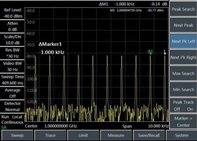
Fig.2 Measurement of pulse repetition frequency
(c) Measure the pulse repetition interval:
Press [Sweep] and [ Sweep Cont Single].
Press [Peak], [Maker][Delta] and [Peak] [Next Peak]. The difference of two markers is the pulse repetition interval (PRI), and its reciprocal is the pulse repetition frequency (PRF).
2. Peak pulse power measurement
Now we have obtained the main lobe amplitude and pulse width. In addition, we can easily obtain the resolution bandwidth of the spectrum analyzer. Therefore, the peak pulse power can be obtained based on such parameters.
In the broad-band measurement mode of the spectrum analyzer:
Peak pulse power = (main lobe amplitude) -(20 log Teff×BWi)
Where:
Teff -pulse width, in second. Second
BWi – impact bandwidth, in Hz
In the narrow-band measurement mode of the spectrum analyzer:
peak pulse power =(main lobe amplitude) -(20 log Teff/T)
Where:
Teff -pulse width, in second. Second
T——pulse repetition frequency
The phenomenon in which the peak pulse power is not equal to the main lobe amplitude is known as pulse desensitization. The sensitivity of the spectrum analyzer will not be decreased by the pulse signal. Accurately, pulse desensitization is caused by distribution of the CW carrier power of pulse modulation to a number of spectrum components (i.e. carrier and sideband). Therefore, each spectrum only contains part of the total power.
Caution:
In measurement of the main lobe amplitude, you should change the attenuator of the spectrum analyzer and verify that the main lobe amplitude will not change accordingly. If the change exceeds 1dB, it indicates that the spectrum analyzer is in the gain compression state. In this case, you must increase the attenuation amount of the attenuator.
