
4051 series signal / spectrum analyzer has good expansion capacity, and can improve the features by means of flexible configuration options and also can construct testing system or redevelop by means of the output interface of all digital and analogue signals. The analyzer is applicable for signal and equipment test of fields including aviation, aerospace, radar detection, communications, electromagnetic countermeasure, and navigation.
4051 Series Signal/ Spectrum Analyzer


Key Features
Wide frequency range from 3Hz to max. 85GHz
Optional extenders extends frequency up to 750GHz
Five analysis bandwidth configuration, maximum analysis bandwidth up to 1GHz
Comprehensive spectrum analysis capability, frequency and FFT sweep supported
Powerful transient analysis and signal playback analysis, frequency-domain and time-domain correlation measurement
10.1 inch high resolution LCD screen, one-button measurement, flexible analog and digital signal output interfaces
Excellent measurement & receiving performance, widely used for comprehensive assessment for the performance of electronic system, and measurement and diagnosis of transmitter and receive
-
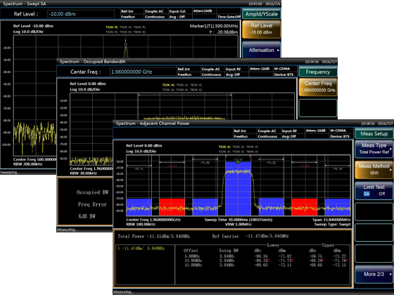
Comprehensive Spectrum Analysis Capability
4051 series signal/spectrum analyzer offer abundant spectrum analysis functions.
• Support frequency sweep and FFT sweep
• Zero span fast sweep, the fastest sweep time is 1μs
• Accurate frequency counting, counting resolution achieves 0.001Hz
• Sweep points number can be arbitrarily selected among 101- 30001
• 6 wave-detection modes, 3 average types
• Support time gate measurement
• Test functions of occupied bandwidth, channel power, adjacent channel power test
• Test functions of power statistics, burst power, harmonic distortion, TOI, spurious emission etc.
• Can be configured with 6 traces, have abundant marker operation functions
-
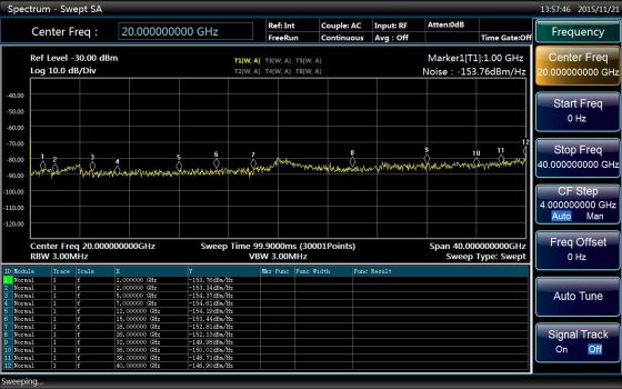
Excellent Test & Receiving Performance
• Wideband preamplifiers (up to 50 GHz) can be configured for the host frequency band.
• 1GHz measurement sensitivity is -156dBm/Hz, and the typical value is -167dBm/Hz with preamplifier
• 50GHz measurement sensitivity is -141dBm/Hz, and the typical value is -150dBm/Hz with preamplifier
• 67GHz measurement sensitivity is -135dBm/Hz
• Full digital IF design, excellent scale fidelity and IF error
-
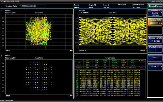
Vector Signal Analysis
Providing flexible demodulation functions of multiple single-carrier digital modulation signals. It can provide vector charts, constellation diagrams, eye diagrams, spectrum diagrams, etc., to analyze the characteristics of the modulation signal.
With comprehensive time domain, frequency domain, modulation domain signal analysis and viewing function, it supports more than 20 modulation system demodulation analysis.
-
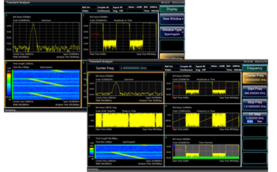
Transient Analysis and Signal Playback Analysis
• Frequency-domain and time-domain correlation test is helpful for understanding and deeply analyzing transient signal events.
• Waterfall diagram display, analyzing the macroscopic law of analysis signal spectrum changing over time.
• Simultaneously analyze the changes of analysis signal frequency, amplitude, and phase over time.
• Support 500M samples (64bits) seamless capture data storage.
• Support multiple storage formats of signal files: CSV, DAT etc.
-
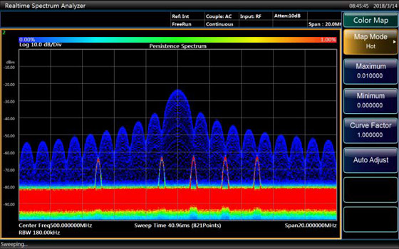
Realtime Spectrum Analysis
4051 series spectrum analyzer can achieve seamless Real-time Spectrum Analysis, and frequency template trigger function, which can be used to trigger, capture, and analyze complex signals.
• Optional 40MHz/200MHz real-time analysis bandwidth
• Digital phosphor spectrum, seamless waterfall, instantaneous spectrum, power vs. time, frequency vs. time and other charts
• 100% POI, Min. duration of the signal: 4.3μs
-
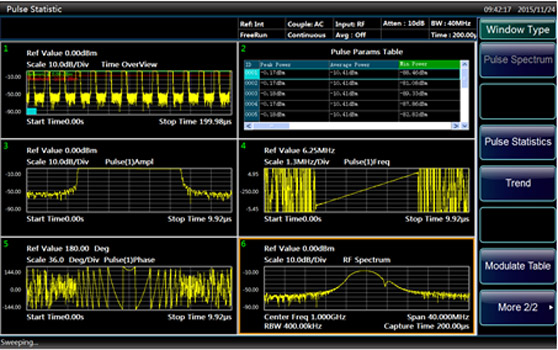
Pulse Signal Analysis
• Pulse signal spectrum and time domain characteristic measurement supports more than 20 kinds of pulse parameters measurement (including time, amplitude, frequency and phase).
• Can perform detailed analysis of amplitude, intrapulse frequency/phase characteristics, and spectral characteristics of arbitrary pulse
• Pulse trend statistics for arbitrary pulse parameters
-
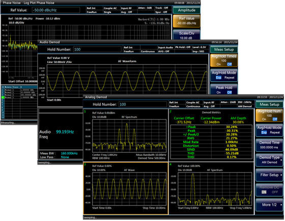
Phase Noise Measurement, Audio Analysis, Analog Demodulation Analysis
• The Phase Noise measurement relies on the excellent phase noise of the signal analyzer and provides one-button automatic measurement to meet the daily signal source phase noise measurement applications.
• Independently optimized audio measurement channel for low frequency signal parameter measurement and analysis.
• Analog Demodulation Analyzer is used to simulate terminal, radio, and general analog modulation source measurement. Demodulate the AM/FM/ΦM signal and measure parameters such as modulation index, modulation distortion, residual FM, and FM linearity and so on.


| Frequency Range | 4051A: 3Hz to 4GHz, 4051B: 3 Hz to 9 GHz, 4051C: 3 Hz to 13.2 GHz, 4051D: 3 Hz to 18 GHz, 4051E: 3 Hz to 26.5 GHz, 4051F: 3 Hz to 40 GHz, 4051G: 3 Hz to 45 GHz, 4051H: 3 Hz to 50 GHz, 4051L: 3 Hz to 67 GHz, 4051N: 3 Hz to 85 GHz |
| 10MHz Precise Frequency Reference | • Frequency accuracy: ± (last calibration date × aging rate + temperature stability + calibration accuracy) • Aging rate: ± 1×10⁻⁷/year • Temperature stability: ± 1.5×10⁻⁸ (20°C ~ 30°C) ± 5×10⁻⁸ (0°C – 55°C) (±1.5×10⁻⁸) • Calibration accuracy: ± 4×10⁻⁸ |
| Span | • Range: 0Hz (zero span), 10Hz – the highest frequency of the model • Accuracy: ± (0.1%× span+span/ (sweep points number-1)) |
| Sweep Time Range | • Span≥10Hz: 1ms – 6000s • Span=0Hz: 1us – 6000s |
| RBW | 1Hz-3MHz (step by 1, 2 ,3 ,5) / 4 MHz / 5 MHz / 6 MHz / 8 MHz / 10MHz / 20MHz |
| VBW | 1Hz-3MHz (step by 1, 2 ,3 ,5) / 4 MHz / 5 MHz / 6 MHz / 8 MHz / 10MHz / 20MHz |
| Signal Analysis Bandwidth | • 10 Hz – 10 MHz (Standard) • 40 MHz (Optional) • 200 MHz (Optional) • 550 MHz (Optional) • 1 GHz (Optional) |
| SSB Phase Noise (Carrier 1GHz, 20℃ -30℃) | Feature • -96 dBc/Hz @ 100Hz offset • -115 dBc/Hz @ 1kHz offset • -125 dBc/Hz @ 10kHz offset • -125 dBc/Hz @ 100kHz offset Typical • -105 dBc/Hz @ 100Hz offset • -118 dBc/Hz @ 1kHz offset • -129 dBc/Hz @ 10kHz offset • -129 dBc/Hz @ 100kHz offset |
| Trigger Source | Free, Line, Video, External level (front panel), External level (back panel), Burst RF, Timer |
| Trigger Detector | Normal, positive peak, negative peak, sample,video average, power average, voltage average |
| 1dB Gain Compression | • 20MHz – 40MHz: -3dBm • 40MHz – 200MHz: +1dBm • 200MHz – 4GHz: +3dBm • 4GHz – 9GHz: -1dBm • 9GHz – 50GHz: +1dBm • 50GHz – 67GHz: -1dBm |
| Residual Response | • 200kHz – 9GHz: -100dBm • All frequency: -100dBm (rated value) |
| Input Connector | 4051A/B/C/D: N (female), impedance: 50Ω 4051E: 3.5mm (male), impedance: 50Ω 4051F/G/H: 2.4mm (male), impedance: 50Ω 4051L: 1.85mm (male), impedance: 50Ω 4051N: 1.0mm (male), impedance: 50Ω |
| Power Supply | AC 100 – 240V: 50 – 60Hz |
| Dimension | Excluding the handle, brackets: 426 (W) × 177 (H) × 460 (D) mm Including the handle, brackets: 510 (W) × 190 (H) × 534 (D) mm |
| Weight | About 25kg (different configuration cause different weight) |
Main Machine
| Module No. | Item | Description |
| 4051A | Signal/ Spectrum Analyzer | 3 Hz to 4 GHz |
| 4051B | Signal/ Spectrum Analyzer | 3 Hz to 9 GHz |
| 4051C | Signal/ Spectrum Analyzer | 3 Hz to 13.2 GHz |
| 4051D | Signal/ Spectrum Analyzer | 3 Hz to 18 GHz |
| 4051E | Signal/ Spectrum Analyzer | 3 Hz to 26.5 GHz |
| 4051F | Signal/ Spectrum Analyzer | 3 Hz to 40 GHz |
| 4051G | Signal/ Spectrum Analyzer | 3 Hz to 45 GHz |
| 4051H | Signal/ Spectrum Analyzer | 3 Hz to 50 GHz |
| 4051L | Signal/ Spectrum Analyzer | 3 Hz to 67 GHz |
| 4051N | Signal/ Spectrum Analyzer | 3 Hz to 85 GHz |
Hardware Options
| Module No. | Item | Description |
| 4051-H01 | Rear Panel RF Input | Postposition of RF signal input interface1 |
| 4051-H02 | High IF Output | Output the second IF signal, the output frequency range 275MHz - 475MHz, step resolution 1Hz. |
| 4051-H03 | IF Output | Output the third IF signal, the output frequency rang 10MHz - 160MHz, step resolution 1Hz. |
| 4051-H04A | Reconstructed IF/ Video Signal Output | To achieve signal output of any IF, AM / FM or I / Q by means of digital reconstruction, with the bandwidth upper limit 40MHz. (Note: H04A&H04B are available for options) |
| 4051-H04B | Wide Band Reconstruct IF/ Video Signal Output | To achieve signal output of any IF, AM / FM or I / Q by means of digital reconstruction, with the bandwidth ranging from 50MHz to 100MHz. (Note: H04B is only available when H38B 200MHz broadband option is selected; H04A & H04B are available for options.) |
| 4051-H08 | Wide Log Detect Output | Output logarithmic detector signal that presents the level characteristics of input signal. |
| 4051-H12A | 40MHz Bandwidth Digital Interface | To output real-time signal acquisition data through optical fiber and support signal data output with maximum 40MHz bandwidth. (Note: H12A is forbidden to choose when H38B is selected; H12B is forbidden to choose when this option is selected, H39 is not available) |
| 4051-H12B | 200MHz Bandwidth Digital Interface | To output instantaneous broadband data by means of optical fiber, support maximum 200MHz bandwidth signal data output. (Note: H12B is only available for selection when H38B 200MHz broadband option is selected; H12A and H39 are not available for selection when this option is selected.) |
| 4051-H12C | 550MHz Bandwidth Digital Interface | To output instantaneous broadband data by means of optical fiber, support maximum 550MHz bandwidth signal data output. (Notes: H12C can only be selected when option H38C with 550MHz broadband is selected;once this option is selected, H12A,H12B and H39 cannot be selected) |
| 4051-H15 | +24V DC Power Supply | Use +24V DC Power Supply |
| 4051-H22A | SAV4711 Data Recorder | Equipping SDD data recorder that has the same interface characteristics to achieve the instantaneous large-number record of signal data. (Note: H22A can only be selected after H12A or H12B digital interface is selected, the capacity selection of the recorded is shown in SAV4711 Recorder files) |
| 4051-H22B | SAV4712 Data Recorder | Equipping HDD data recorder that has the same interfa ce characteristics to achieve the instantaneous large-nu mber record of signal data. (Note: H22A can only be s elected after H12A or H12B digital interface is selected, the capacity selection of the recorded is shown in SAV 4712 Recorder files) |
| 4051-H33 | Electronic Attenuator | Frequency Range 3Hz - 4GHz, attenuation range 0-30dB,1dB stepping. |
| 4051-H34-04 | Low-Noise Preamplifier | Either Low-band preamplifier or full-band amplifier is available for option. Under the circumstance when full-band preamplifier is chosen, and noise optimization path of 4GHz or above frequency is provided.(Note: Low-wave preamplifier number is H34-04, full-band preamplifier is selected according to the frequency limit of the selected signal analyzer. eg, 4051E frequency range up to26.5GHz should choose 4051-H34-26. |
| 4051-H34-09 | Low-Noise Preamplifier | Same as mentioned above |
| 4051-H34-13 | Low-Noise Preamplifier | Same as mentioned above |
| 4051-H34-18 | Low-Noise Preamplifier | Same as mentioned above |
| 4051-H34-26 | Low-Noise Preamplifier | Same as mentioned above |
| 4051-H34-40 | Low-Noise Preamplifier | Same as mentioned above |
| 4051-H34-45 | Low-Noise Preamplifier | Same as mentioned above |
| 4051-H34-50 | Low-Noise Preamplifier | Same as mentioned above |
| 4051-H36 | Pre-selector Bypass | The tracking pre-selector in the bypass receiving channel. (Note: option H36 is needed together with H38A,H38B and H38C to provide the best wideband signal receiving characteristics) |
| 4051-H38A | 40MHz Analysis Bandwidth | Support 10Hz-40MHz Analysis Bandwidth (Note: option H38A and option H36 should be selected together to provide the best wideband signal receiving characteristics, H38B and H38A are no need to be selected at the same time) |
| 4051-H38B | 200MHz Analysis Bandwidth | Support 10Hz-200MHz analysis bandwidth (Note: option H38B and option H36 should be selected together to provide the best wideband signal receiving characteristics, H38A, H38B and H38C can not be selected at the same time) |
| 4051-H38C | 550MHz Analysis Bandwidth | Support 10Hz-550MHz analysis bandwidth (Note: option H38C and option H36 should be selected together to provide the best wideband signal receiving characteristics, H38B and H38C are no need to be selected at the same time) |
| 4051-H39 | Audio Analysis | Fulfill audio signal parameter test, distortion test and waveform analysis. (Note: H12A& H12B are unavailable when this option is selected) |
| 4051-H40 | External Mixer | Provide external mixing methods to extend range measurement capability. This option provides local oscillator input, IF input function and signal-recognition function. (Only 4051A is not available, Extended frequency depends on the selected extending module, extending module is optional part) |
| 4051-H41 | Realtime Analysis | Provide digital phosphor spectrum and seamless waterfall, including frequency template trigger, which can support real-time spectrum analysis of 200MHz bandwidth. (Note:The maximum real-time analysis bandwidth is determined by the bandwidth options of the instrument configuration, H38A and H38B.) |
| 4051-H48 | Noise Figure Measurement | Noise source drive and noise figure measurement function (S3503L exception) |
| 4051-H97 | Mounting Suit | Handles and accessories for 4051 mounting on standard racks. |
| 4051-H99 | Aluminum Alloy Aviation Case | For safety transport. |
Software Options
| Module No. | Item | Description |
| 4051-S01 | Absolute Power Measurement | High-precision measurement of RF signal power by connecting an external USB power probe. |
| 4051-S04 | Phase Noise Measurement | Provide unilateral band phase noise curve and one-point band phase noise testing capability. |
| 4051-S09 | Analogous Demodulation Analyzer | Fulfill modulation and distortion characteristics analysis of AM, FM, PM signals. |
| 4051-S10 | Transient Analyzer | Fulfill the testing analysis of signals’ instantaneous parameter spectrum, spectrum range and all sorts of modulation features; support the playback of recorded data. |
| 4051-S12 | Vector Signal Analyzer | Provides flexible demodulation functions of multiple single-carrier digital modulation signals. It can provide vector charts, constellation diagrams, eye diagrams, spectrum diagrams, etc., to analyze the characteristics of the modulation signal. The modulation error of the signal can be obtained by demodulation, which helps to judge the cause of the signal error. |
| 4051-S13 | Pulse Signal Analyzer | Automatically measure time, electrical level and modulation parameters of pulse wave and statistical analysis of pulse sequence. |
| 4051-S40 | WLAN 802.11a/b/g Measurement | Broadband wireless LAN protocol physical layer test (802.11a/b/g), covering radio frequency, modulation analysis, and modulation quality testing. |
| 4051-S40N | WLAN 802.11n Measurement | Broadband wireless LAN protocol physical layer test (802.11n), covering radio frequency, modulation analysis, and modulation quality testing. |
| 4051-S40AC | WLAN 802.11ac Measurement | Broadband wireless LAN protocol physical layer test (802.11ac), covering radio frequency, modulation analysis, and modulation quality testing. |
| 4051-S40AX | WLAN 802.11ax Measurement | Broadband wireless LAN protocol physical layer test (802.11ax), covering radio frequency, modulation analysis, and modulation quality testing. |
| 4051-S51 | DTMB Signal Test | Provide one-button power and modulation analysis functions that comply with the DTMB standard. |


