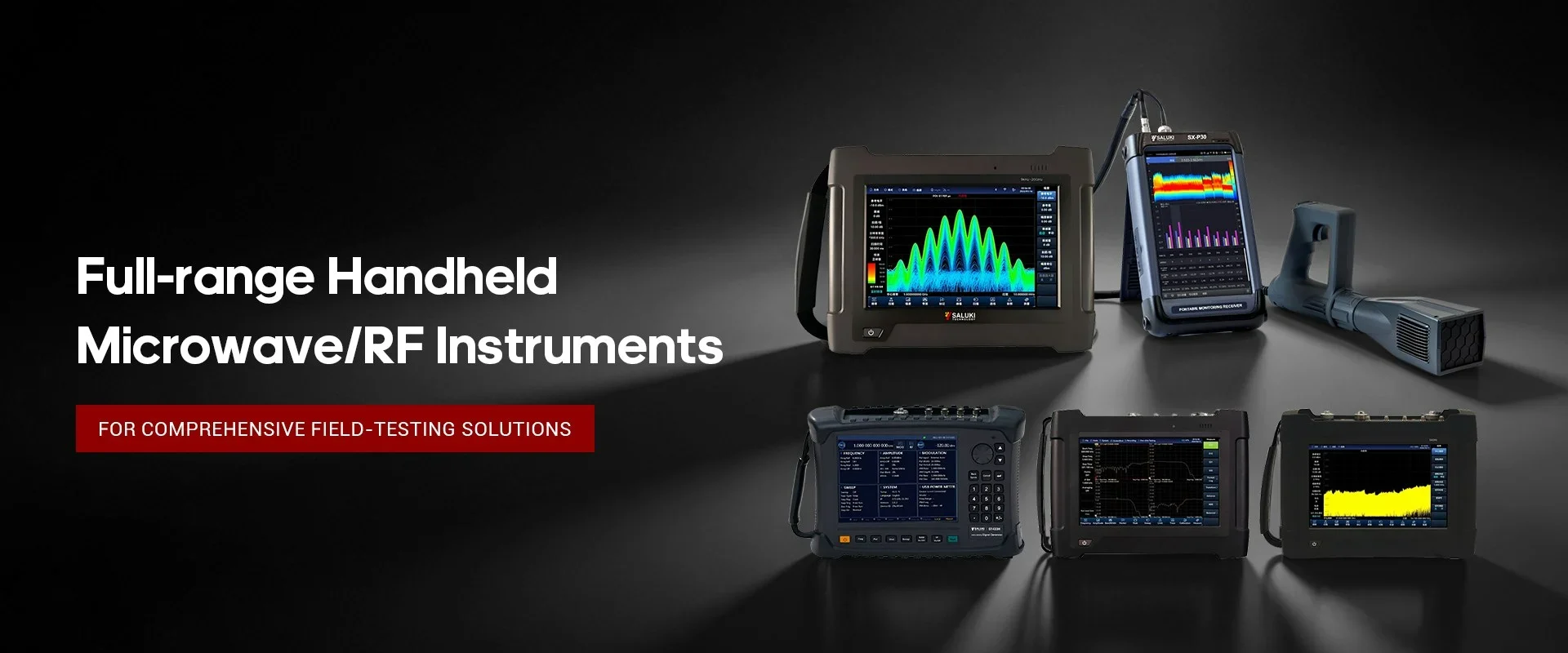
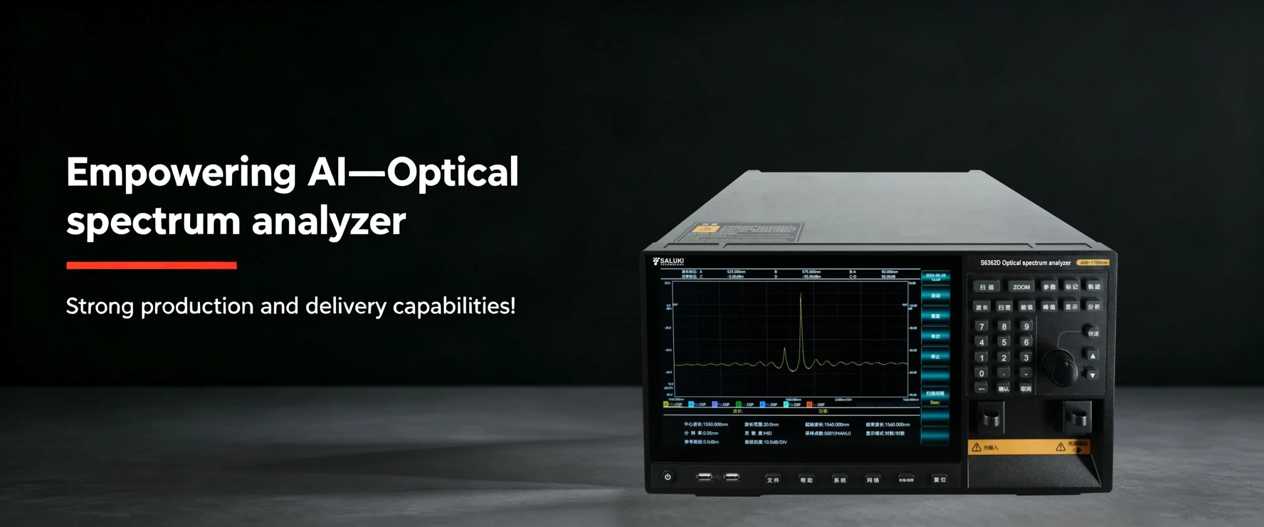
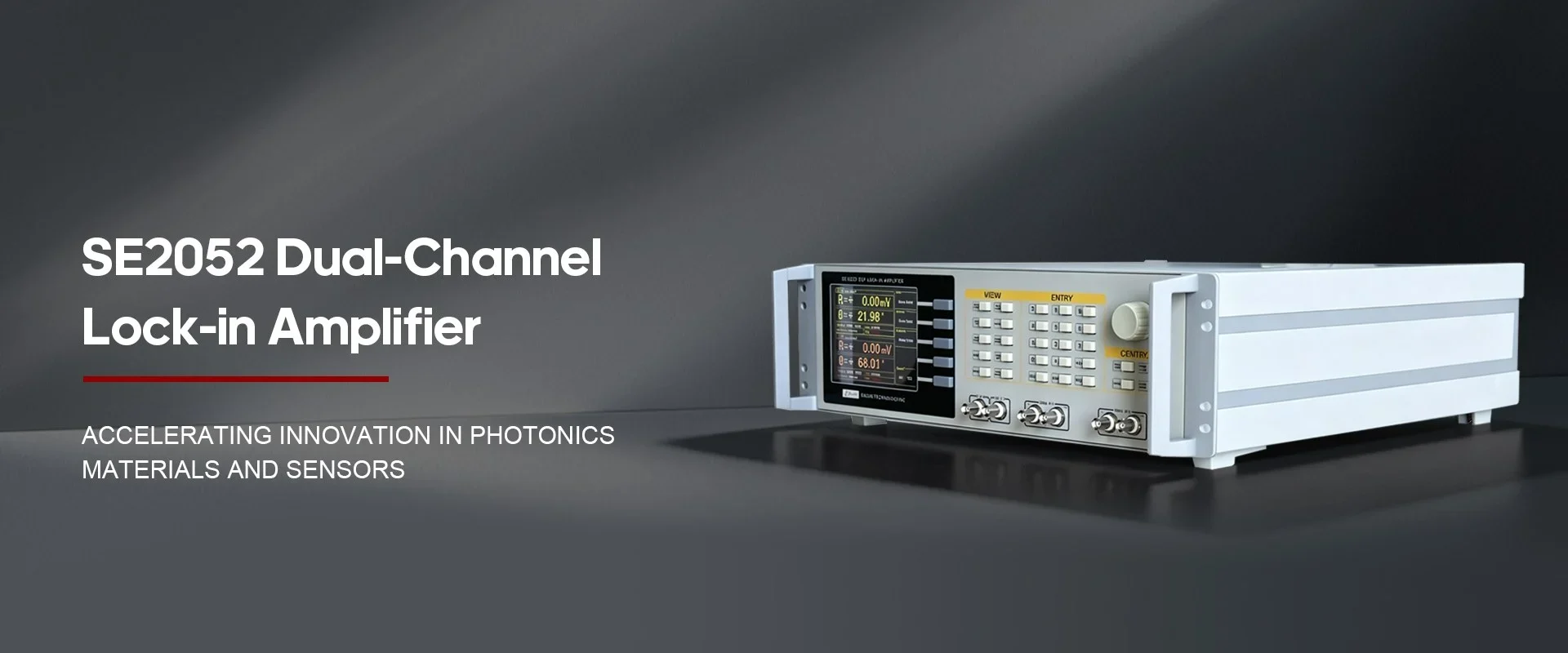
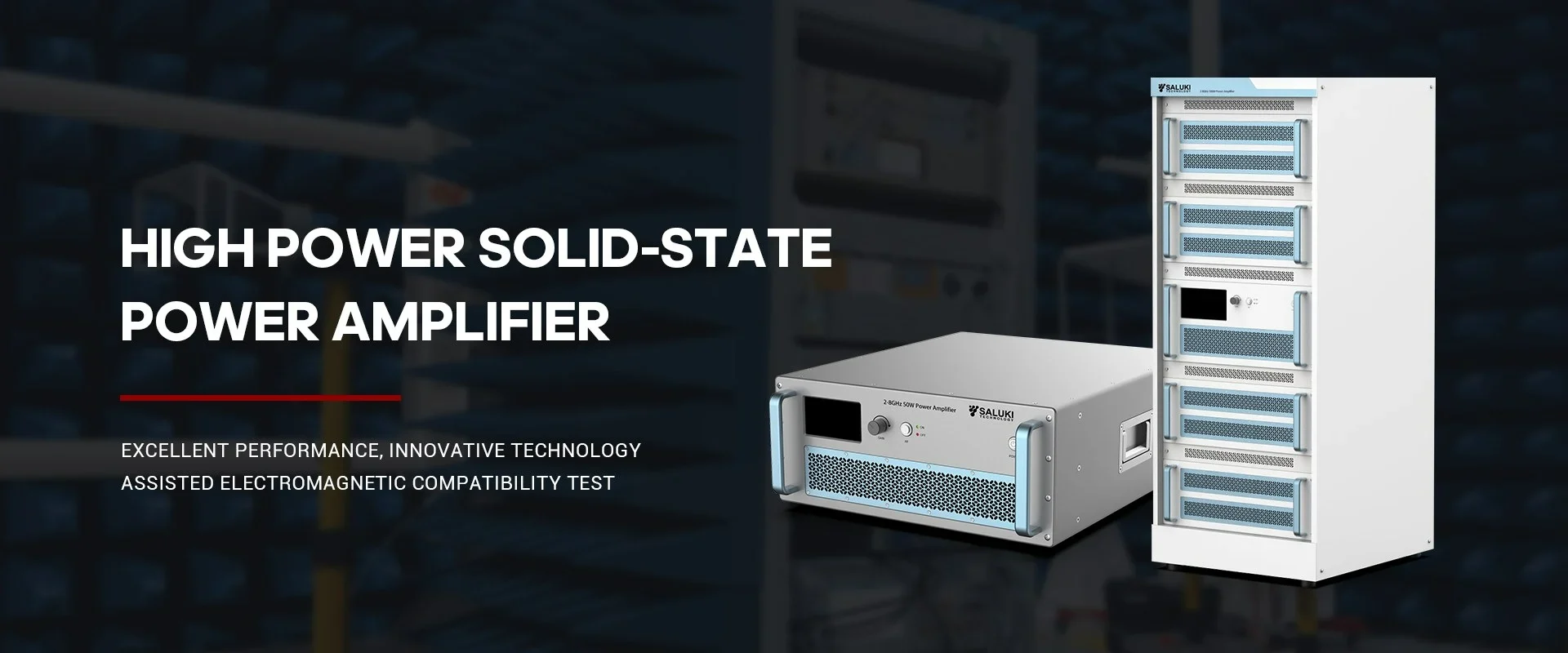

Best Selling Products
Contact us: sales@salukitec.com
As a professional RF, microwave, and millimeter-wave products manufacturer and supplier in China.
Whether you’re a reseller, distributor, solution provider, or startups, we have a solution to help you grow your business and bring new solutions to market. We believe it is a great opportunity for you to grow with us.

Company Profile
Overview
Saluki Technology Inc. is a high-tech company, supplier and manufacturer of High-end RF&MW Test Equipment, General Test Equipment, Lab Equipment and Optical Communication Equipment. Founded in 1997, the company was initially an agent of telecommunication equipment, and it once ranked second in the Chinese market. With an in-depth understanding of the market and user needs, meantime a deep accumulation of technology, the company began to develop its own brand of test equipment in 2008, and promoted it mainly for the Asian market. Beginning in 2015, the company moved its headquarters to Taiwan, and began to face more overseas markets and built the SALUKI brand.
At present, the company has exclusive agents in South Korea, Turkey, and stable partners in markets of countries like Canada, Germany, the United States, the United Kingdom, Finland, Poland, Indonesia, Israel, Vietnam, and South America.
We are committed to establishing a stable partnership with local agents to provide customers with the most professional, fast and long-term services.
Our Vision
Accurate, Fast and Reliable
-
20+
Work Experiences
-
100+
Sales Engineers
-
10+
Branch Openings
We can also provide the following brands
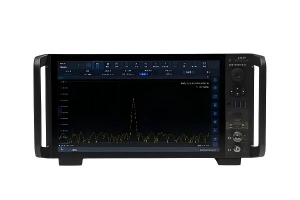
Saluki S3331 handheld spectrum analyzer is designed for field use. It has a low weight, compact structure and a good performance. S3331 handheld spectrum analyzer has many functions, including continuous signal measurement, N dB bandwidth measurement, channel power measurement, occupied bandwidth measurement, weak signal capture, harmonic distortion measurement, etc..
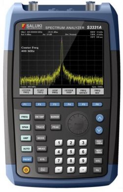
Fig.1 S3331 handheld spectrum analyzer
The following are common problems about S3331 handheld spectrum analyzer.
1. Start S3331 but the screen does not light:
Please following the procedures below
(1) Check whether the fan is running:
A. If the fan runs normally, it is possible that the display cable is loose. Please contact Saluki.
B. If the fan does not run, the instrument does not start normally. In this case, check steps (2), (3) or (4).
(2) If using battery powered: Make sure the battery is in good condition and installed correctly.
(3) If the instrument is powered via adapter: Make sure the power adapter model is correct and working well.
(4) If the power is ok, but the instrument does not work, the fuse inside may be burned. Please contact Saluki.
2. Keys not respond or the response is incorrect:
(1) If all the keys are not responding, it is possible that the keyboard cable is loose.
(2) If the key value is wrong, there may be damage on keyboard, please contact Saluki to repair.
3. No signal display after normal power on:
If the monitor does not display the signal, please follow the steps below:
(1) Connect 10MHz reference outputs port to RF input port
(2) If there is no signal Display, there may be machine hardware failure, please contact the manufacturer to solve.
4. The frequency of the signal display is not accurate:
During the measurement, the read signal frequency exceeds the acceptable error range or the signal is shaking on the display:
(1) Check if the input signal is stable, and if so, check in step 2.
(2) Check whether the internal and external reference of the spectrum analyzer is normal, and select the reference for internal reference or external reference according to different test conditions: Press [Frequency] [Frequency reference internal external].
(3) If the problem is not solved, please contact Saluki.
5. The amplitude of the signal is not accurate:
The amplitude of the signal is inaccurate.
Recalibration: Set a signal generator frequency 440MHz, power -20dBm, connect this signal to the RF analyzer RF input port, click: [System] [Next] [Next] [User calibration] [Start calibration].
If the problem is not solved after recalibration, please contact Saluki.
