
In the power measurement, users often have some specific application scenarios when using the microwave power meter. For on-site users, they need to manually reconfigure the parameters each time they use it, and for program-controlled users, a large number of program-controlled commands need to be sent, which is prone to programming errors.
Saluki S2438 series microwave power meter provides the [SAVE RECALL] function to save and recall the current parameter status of the power meter to solve the issue above, and a lot of duplication of work can be avoided.
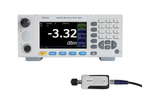
Fig.1 S2438 series microwave power meter and power sensor
The following uses the S2438 series microwave power meter channel A to connect the S81702 power sensor as an example to illustrate the effectiveness and convenience of the “store/recall” function for on-site and program-controlled users.
Suppose the user has the following specific application scenarios when using the “Gate” function to measure pulse parameters:
Meas 1: Measure the average power of gate 1 of channel A, that is, the signal pulse power;
Meas 2: Measure the peak power of gate 1 of channel A, that is, the signal peak power;
Meas 3: Measure the average power of gate 2 of channel A, that is, the average power of signal pulses;
Meas 4: Measure the power value of channel A gate 3 average power minus gate 4 average power, that is, the signal pulse drops.
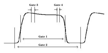
Fig.2 Gate schematic diagram
The parameter setting of the power meter as below :
(1) Click [Channel] —> [Gates Set] —> [Now Gate], set the start time and length of Gate 1,2,3, 4 separately.
(2) Click [Window] to display dual measurement windows.
(3) Click upper window [Display] —> [Disp Type], select double value.
(4) Click lower window [Display] —> [Disp Type], select double value. Now, the screen will display 4 measurement windows, named Meas 1, 2, 3, 4.
(5) For Meas 1, click [Measure] —> [Feed] —> [Gate], select Gate 1, select “AVG PWR” at [Meas], and select “Sing” mode at [Function].
6) For Meas 2, click [Measure] —> [Feed] —> [Gate], select Gate 1, select “Peak PWR” at [Meas], and select “Sing” mode at [Function].
7) For Meas 3, click [Measure] —> [Feed] —> [Gate], select Gate 2, select “AVG PWR” at [Meas], and select “Sing” mode at [Function].
8) For Meas 4, click [Measure] —> [Feed] —> [Gate], select Gate 3, select “AVG PWR” at [Meas], select “Comb” mode at [Function]. Then click [Feed2] —> [Gate], select Gate 4, select “AVG PWR” at [Meas], and switch “F1-F2” mode at “Comb”.
Operation step for on-site user:
Set the [System]—> [Save Recall]—> [Save] function to store the current parameter status, and you can also edit the status name by setting [System] —> [Save Recall] —> [Edit]. For example, set the status name as “userConfig”. After that, each time you turn on the power host and select the desired state, set the [System]>[Save Recall]>[Recall] function to set the parameter status with one key.
Operation step for program-controlled user:
Set the [System] —> [Save Recall] —> [Save] function to store the current parameter status. After that, every time turn on the power host, user only need to send the following program control commands to get the measurement results.
(1) *RCL 1 Call the parameter status of the register “userConfig”
(2) MEAS1? Start a measurement and return to Meas 1 power measurement value
(3) FETC2? Query Meas 2 power measurement value
(4) FETC3? Query Meas 3 power measurement value
(5) FETC4? Query Meas 4 power measurement value
