
In the power meter mode of S3302 series spectrum analyzer, the USB interface is connected with an external USB power sensor through the USB cable to test the power. Using S8723X USB power sensor provided by SALUKI., RF/microwave signals up to 40GHz can be tested, and the true average power with high dynamic range from -60dBm to +20dBm can be measured. The measurement reading will be shown on the display interface of the USB power meter mode of S3302 series. The block diagram of the test is shown in Fig.1. The attenuator can be added according to the needs.
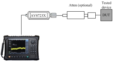
Fig.1 Power Meter Structure
The power meter interface is shown in Fig.2 (an example).
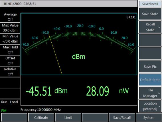
Fig.2 Power Meter Interface
It is recommended to purchase the USB-based high-performance microwave power sensor, which is also provided by SALUKI.. The following models are mainly available, and you can purchase the power sensor according to test needs.
• S87230: 9kHz to 6GHz, -50dBm to +20dBm, N(m)
• S87231: 10MHz to 18GHz, -60dBm to +20dBm, N(m)
• S87232: 50MHz to 26.5GHz, -60dBm to +20dBm, 3.5mm(m)
• S87233: 50MHz to 40GHz, -60dBm to +20dBm, 2.4(m)
Connection of power sensor:
1) Connect the small end of the USB cable to S8723X USB power sensor.
2) Connect the large end of the USB cable to the USB interface of the spectrum analyzer. The green indicator of the power sensor will be ON a moment later.
3) The USB power sensor can be shut down after the USB cable is removed. In this case, the green LED indicator will be OFF.
