When we talk about analog modulation, we are referring to amplitude modulation (AM), frequency modulation(FM) and phase modulation(PM). Nowadays, many spectrum analyzers support analog signal analysis functions to help users quickly get the basic parameters of a modulated signal. In this article we will take S3302 series handheld spectrum analyzer as an example to show how analog demodulation function working.
The AM-FM-PM analyzer mode is used for displaying the spectrum of AM, FM and PM signals and analyzing relevant parameters. The main spectrum and relevant parameters are shown below:
• RF spectrum: Similar to the spectrum analyzer mode, the frequency spectrum of the modulation signal will be displayed, and the occupied bandwidth can be measured.
• Audio spectrum: Display the frequency spectrum of the demodulated audio signal.
• Audio waveform: Display the waveform of the demodulated audio signal within the time domain.
• Parameter analysis: Measure and analyze the carrier power, modulation rate, carrier offset, modulation depth (AM), modulation frequency offset (FM), modulation phase deviation (PM), S/N, modulation distortion and total harmonic distortion of the modulated signal.
Three windows can be displayed at the same time or respectively in the AM-FM-PM analyzer mode. Press [Measure] and select [RF Spectrum], [Audio Spectrum], [Audio Waveform] and [Summary] to display one or all spectrum(s).
In order to better observe the measured signal, the following steps can be taken:
1) Press [Measure] [Demod Type AM FM PM] to select the type of the analog signal to be demodulated.
2) Press [Frequency] [Center Freq] and set the center frequency of the measured signal.
3) Press [BW][IFBW], and set the appropriate IF bandwidth with the number keys or [↑] or [↓] key or knob.
4) Press [Amplitude][Ref Level] and set the reference level of the RF spectrum. Press [Scale/Div] and set the appropriate scale/division to facilitate the viewing of RF spectrum.
5) Press [Audio Spectrum] [Span] and set the appropriate span. Press [Scale/Div] and set the appropriate scale/division to facilitate the viewing of the frequency spectrum of the audio signal.
6) Press [Audio Waveform] [Sweep Time], and set the display time of the audio signal waveform. Press [Scale/Div] and set the appropriate scale/division to facilitate the viewing of the frequency spectrum of the audio signal.
Note: Set the appropriate IF bandwidth. The IF bandwidth should be more than the width of the modulation signal, so as to accurately demodulate the signal. You can observe the bandwidth in the RF spectrum. At the same time, noise may be produced in the case of too large IF bandwidth, which will affect the accuracy of parameter measurement.
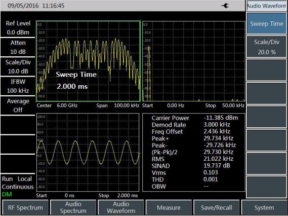
Taking the FM signal measurement for example, the AM-FM-PM analyzer mode is introduced as follows. At first, input the FM signal generated by one signal source to the RF input end of the instrument. Set the signal frequency as 6GHz, amplitude as -10dBm, modulation rate as 3kHz and modulation offset as 30kHz. Measurement procedures are as follows:
1) Press [Measure] [Demod Type AM FM PM] and select FM.
2) Press [Frequency] [Center Freq] and set the center frequency of the measured signal as 6GHz.
3) Press [BW] [IFBW] and set the IF bandwidth as 100kHz.
4) Press [Audio Spectrum] [Span], and set the span as 50kHz.
5) Press [ [Audio Waveform] [Sweep Time] and set the sweep time as 2ms.
Measurement results are shown in figure 1.