
The vector network analyzer is an instrument that measures the network parameters of electrical networks. Saluki S3602 vector network analyzer is a new generation of vector network analyzer, launched by Saluki Technology. S3602 VNA can be widely applied in measurement of the transmission/reception (T/R) module, dielectric material properties, microwave pulse characteristics and photoelectric properties. It is an indispensable tester in research and production of the phased array radar, communication, RF microwave device and other systems.
Many methods can be applied to adjust the setting and optimize the measurement accuracy by using S3602 network analyzer. In this section, we mainly introduce how to reduce the noise on the measurement trace by the network analyzer function. The following functions of the analyzer can help to reduce the influence of trace noise.
1. Sweep Averaging
(1) Sweep averaging
a) Sweep averaging is a function to reduce the influence of random noise on the measurement.
b) Each data point is calculated based on the average value of several continuous sweep operations. The times of continuous sweep are determined according to the setting of the averaging factor.
c) The average value of tracks will be applied on all measurements of one channel, and the average number of each channel will be displayed.
d) The noise reduction and dynamic range can be improved by increasing the averaging times.
e) The noise reduction effect of sweep averaging is the same as that of reduction of the IF bandwidth.
(2) Influence of sweep averaging
As shown in Fig.2, sweep averaging has influence on measurement results.
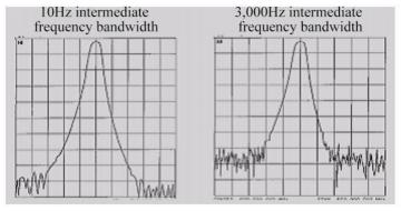
Fig.1 Influence of sweep averaging on measurement results
(3) Setting of sweep averaging
Menu path: [Response] > [Average] > [Average…].
Select [Average on/OFF] to enable the averaging function.
Directly enter the value in the [Averaging factor] box or increase/decrease the averaging times of the analyzer with the arrow button.
2. Trace Smoothing
The smoothing function is used to reduce the peak-peak noise of broadband measurement data. The data of part of the displayed trace are averaged by the analyzer. The number of adjacent data points subject to averaging at the same time is also known as the smoothing aperture. The aperture can be defined as the number of data point or the percentage of X-axis span.
(1) Influence of trace smoothing
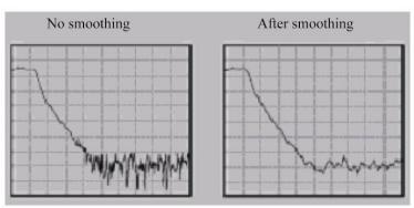
Fig.2 Influence of trace smoothing on measurement results
(2) Setting of trace smoothing
Menu path: [Response] > [Average] > [Smooth…].
Click [Smooth] to enable the smoothing function.
Select the method to specify the value of the smoothing aperture:
a) Enter the smoothing percentage in the [Smoothing percentage] box. (Max. 25%)
b) Enter the number of smoothing points in the [Number of smoothing points] box. (The maximum value is 25% of the total number of scanning points of the test.)
3. Intermediate Frequency Bandwidth
You can reduce the bandwidth of the IF receiver so as to reduce the influence of random noise in measurement. Once the IF bandwidth is reduced by 10 times, the base noise will be reduced by 10dB. However, if the IF bandwidth is small, the sweep time will be long. The signal received by the analyzer will be changed into the IF (7.606MHz) from the network analyzer can change the received signal from the RF/microwave frequency into the IF (7.606MHz). The bandwidth of the IF band pass filter can be reduced from 5MHz to 1Hz (min.). The IF bandwidth can be independently set for each channel or in segment sweep.
(1) Reduction of influence of IF bandwidth
The influence of the IF bandwidth on measurement results.
(2) Setting of IF Bandwidth
Menu path: [Response] > [Average] > [Intermediate frequency bandwidth…].
Directly enter the value in the [Intermediate frequency bandwidth] dialog box or select the value with the arrow button.
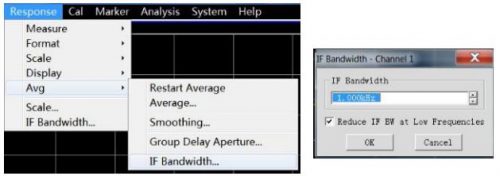
Fig.3 Setting of Intermediate Frequency Bandwidth
