Using an external bridge/coupler is a better way. You only need to choose the product according to the frequency band you use, and the operation is also very simple.
Considering that other models of the SK9901 series can directly support low frequencies of several kHz, this article mainly considers high-frequency use, so directional couplers are the best choice.
When choosing a coupler, you don’t need to worry about its lower limit frequency. For common broadband couplers (those with a bandwidth of more than 30% of its upper limit frequency), when it is far below its lower limit frequency, only the coupling degree is reduced, and the directivity is still good.
SK9901Q has a good dynamic range at lower frequencies, and the reduction in coupling has no effect on reflection measurement. Of course, too short coupling lines will be sensitive to the phase of reflection, but the impact can be eliminated to a certain extent by the calibration model. The following example shows that for a broadband fixed coupler with a nominal lower limit frequency of 26.5GHz, it is barely possible to use tens of MHz.
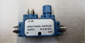
The figure below is the fixed coupler selected in this tutorial, with a nominal frequency range of 26.5-40GHz
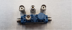
Since the fixed coupler uses a 2.4mm connector and is incompatible with SMA, it is first converted to the 2.92 standard with an adapter.
The output port (port 1) of SK9901Q is connected to the fixed coupler through a 10dB attenuator. Note that the fixed coupler is usually marked with the forward coupling direction, so it should be used in reverse, with its OUT end as the input. The purpose of using the attenuator is to absorb the reflected wave of the device under test as much as possible and improve the port matching.
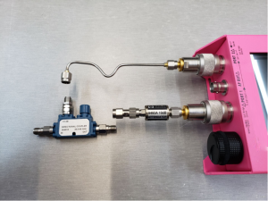
After installation, it is shown in the figure below. Use a semi-steel wire to connect the coupling end of the fixed coupler to the input port (port 2) of SK9901. If you need to use frequencies above 10GHz, semi-steel wire is the cheapest and most effective solution (better than phase-stable cable), otherwise the phase will drift after shaking, which will make the operation experience very poor.
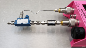
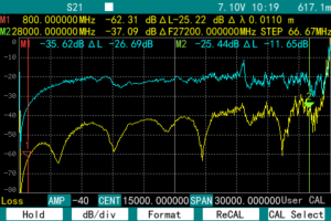
After connecting, you can use the S21 function to observe the coupling degree, and measure a curve when the end is suspended and connected to the load. The more the curve drops when the load is connected, the better.
The fixed coupling used in this article has a coupling degree of -10dB. Since a 10dB attenuator is connected in series, the blue curve in the figure below (when the end is suspended) hovers around -20dB. The yellow curve is the signal coupled when the load is connected. It can be seen that at most frequencies, it has a directivity better than 20dB. The deterioration of directivity above 26GHz is more likely caused by the reduction of the dynamic range of SK9901Q in this frequency band. In addition, the load and attenuator used in this article cannot reach such a high frequency.
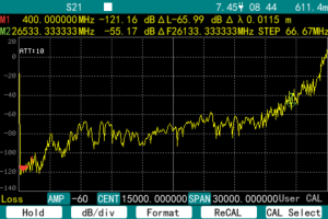
The figure below is the S21 noise floor of SK9901Q. It can be seen that the dynamic range decreases rapidly above 26G, so it is understandable that the directivity of the high frequency band in the above figure is reduced.
After checking the directivity of the fixed coupling, switch to S11 mode, and then press the RECAL key on the soft menu to calibrate the instrument.
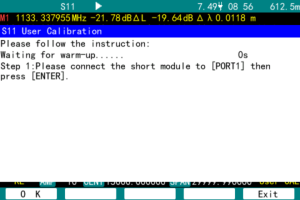
Connect the short circuit, open circuit and load respectively according to the prompts. The parameters of the calibration kit are provided by the manufacturer of the calibration kit and need to be entered in “CAL KIT DATA” under the FUNC menu. After the calibration is completed, the S11 noise floor when the load is connected is displayed. It can be seen that except for zero frequency, the entire display range below 24GHz is better than 40dB. The specific measurement performance depends on the performance of the calibration load.
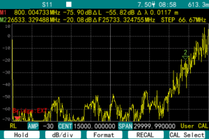
Connect an open circuit or a short circuit to the port to view the return loss during total reflection. As shown in the figure below, it fluctuates around 0.
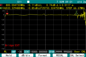
The reason for not strictly returning to 0 is that the finished calibration kit is more expensive than 901Q. In order to be down-to-earth, we temporarily DIY one and enter the parameters as 0.

Let’s measure the reflection of a 10.5GHz low-pass filter.
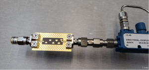
It can only be said that it is roughly like that.
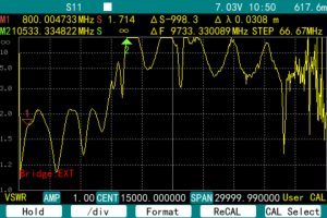
It should be noted that at a span as large as 30G, the distance between each scanning point of the instrument is as high as 66.67MHz. If it is used to measure low frequencies, such a large scanning interval will definitely miss most of the resonance peaks, such as no point in the entire shortwave frequency band. Therefore, when measuring low-frequency antennas, the SPAN must be reduced and the measurement must be calibrated under a small sweep width.
The figure below shows that a walkie-talkie antenna is measured. At this time, the SPAN is set to 1GHz, and the leftmost side of the screen is zero frequency. It can be used after calibration.
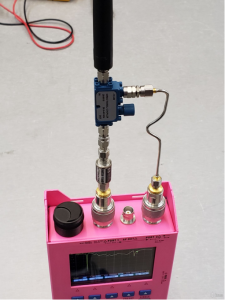
It shows that the antenna has a low standing wave near 140MHz.
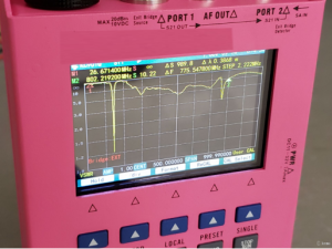
For this unbalanced antenna, the shell of the instrument is equivalent to a “ground grid” and participates in the antenna radiation. Therefore, the measured parameters will be very different depending on whether the hand holds the instrument or not. At the moment of screenshot, the hand must hold the instrument to operate the keyboard, and cannot be untouched as in the above figure, so the obtained curve is different (as shown below). The curves of using a desktop instrument and a handheld instrument will also be significantly different due to the different shapes of the instruments. For unbalanced antennas, it is necessary to measure on a quasi-infinite ground plane or on a dedicated test fixture (as close to the actual use environment as possible, such as the housing of a walkie-talkie).
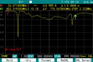
In fact, the above-mentioned 40GHz directional coupler can be used to measure shortwave antennas. However, in a two-port vector network, because the forward signal of the transmission test is also taken from the coupling end, too low a coupling degree will result in almost no dynamic range. In addition, too low a coupling degree is easily affected by changes in the external environment and drifts, so don’t think about using a simple coupler to get a two-port vector network.
The safest way is to use a coupler that covers the frequency band to be measured. After all, not all forms of couplers can work at low frequencies.


