
Experiment name: Application of power amplifier in dry-coupled ultrasonic testing system
Research direction: Research on sound pressure gain at the focus of high-efficiency Fresnel acoustic lens in water
Experimental content: First, a dry-coupled ultrasonic detection system was constructed, and a dry-coupled probe with a special structural form of piezoelectric vibrator and sound-transmitting rod was designed. Then a dry coupled ultrasonic imaging method based on time reversal is proposed, and the principle of dry coupled ultrasonic time reversal focusing is analyzed. Through the extraction of damage scattering signals, time reversal and secondary loading, the transient fluctuation diagram at the focusing moment is established. Finally, through Defects are imaged in two ways: summing and multiplying the signal amplitudes of structural elements.
Test purpose: To solve the problem of not being able to apply couplant on the surface of the bonding structure of the solid rocket motor casing during ultrasonic testing.
Test equipment: dry coupling probe, ultrasonic pulse generator and receiver, preamplifier, digital storage oscilloscope card, probe tooling, SLA-HVP-218 power amplifier, signal generator, oscilloscope, computer.
Experiment procedure:
(1) Time reversal method of dry coupled ultrasound;
The process of dry-coupled ultrasonic time-reversal focusing is shown in the figure. First, the piezoelectric oscillator in the dry-coupled transmitting probe is excited by the inverse piezoelectric effect to generate ultrasonic waves, which are transmitted into the composite specimen through the sound-transmitting rod; then, Multiple dry-coupled receiving probes receive the scattered signals from defects in the board at different positions on the test piece; secondly, the received signals are processed by time reversal, amplification and delay, and the original receiving probe is used as the transmitting probe, and the processed The signal is reloaded and transmitted; finally, the signal is collected and received twice, and the signal produces a focusing amplification effect at the wave source.
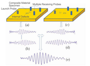
Dry coupled ultrasonic time reversal process
(2) Dry coupled ultrasonic detection system;
First, the ultrasonic pulse generator and receiver are excited to generate a pulse signal of a certain frequency, which is loaded on the piezoelectric vibrator in the dry coupling probe. Under the influence of the inverse piezoelectric effect, ultrasonic waves are generated and propagate in the plate in the form of guided waves and are received. After being received by the probe, the ultrasonic waves are converted into electrical signals due to the influence of the piezoelectric effect. The electrical signals are amplified by the preamplifier and collected and stored by a digital storage oscilloscope card and displayed on a PC.
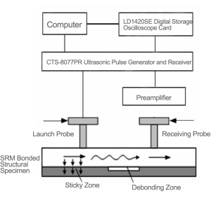
Working principle of dry coupled ultrasonic inspection system
(3) Experimental verification;
This paper uses a 5-period Hanning window modulated sinusoidal function as the excitation signal, with a frequency of 70 kHz, a signal repetition frequency of 1 kHz, a peak-to-peak voltage of 2V, and a power amplifier amplification factor of 20 times. During detection, the PC modulates the excitation signal first and sends it to the signal generator. The set detection parameters are amplified by the SLA-HVP-218 power amplifier and then loaded to the transmitting probe. In addition, receiving probes are arranged at each detection position of the test piece and connected to the oscilloscope. , in order to keep the coupling pressure of each detection probe consistent, the same quality steel block is used for pressurization. At the same time, connect the Trigger terminals of the oscilloscope and the signal generator to keep them synchronized, and use the rising edge of the square wave for trigger control. After USB communication, the synchronous display and storage of data collected by each channel of the oscilloscope can be realized in the LabVIEW environment. The stored signal data can be intercepted, inverted, amplified, etc., and re-sent to the signal generator for loading, and the transmission/exchange Receive the probe cable and collect the final focus amplification signal, thus forming a closed-loop process of the entire time reversal operation.
Test Results:
According to the law of guided wave propagation, the relationship between the focusing moment t and the arrival damage time t is: t, = tw -ta= 0.4 ms. Taking f=0.1mm, the propagation speed of ultrasonic waves in steel is 3 100 m/s , the abscissa range is 0 ~ 160 mm, and the ordinate range is 0 ~ 80 mm. The final damage imaging is obtained according to the summation and product forms, as shown in the figure. The image obtained by using ultrasonic water immersion C scanning is as shown in the figure.
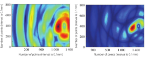
Damage imaging obtained in summation form (Left)
Damage imaging obtained in quadrature form (Right)
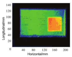
Ultrasonic water immersion C-scan image
(1) The dry coupling detection signal will produce a focus amplification effect after time reversal, secondary loading and emission, and the energy located at the defect will be the largest;
(2) By collecting, time reversing and extracting the envelope of the damage scattering signal, the transient fluctuation diagram at the signal focus moment was established, and the dry coupling time reversal imaging detection method was preliminarily verified based on the experimental data.
The performance of the SLA-HVP-218 power amplifier in this experiment: amplifying the signal and loading it to the transmitting probe.
