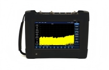
The frequency range of Saluki S5109 microwave analyzer product covers 9 kHz / 300kHz to 54 GHz, with various measurement functions such as spectrum analysis, dual-port vector network analysis, antenna feeder analysis, vector voltmeter, USB CW/ pulse power measurement, OTDR, optical power meter, field strength measurement, IQ analys is, interference analysis, analog demodulation analysis, 40 MHz bandwidth real-time spectrum analysis, etc. The product is a handheld form, 10.1-inch LCD touch screen, working temperature is -20℃-55℃, support battery power supply, small size, light weight, easy to control, can be used in the field of electronic communication maintenance guarantee test of communication equipment.
S5109 Series Microwave Multifunctional Analyzer

Key Features
Wide frequency range coverage
Excellent performance specifications
Abundant measurement functions
Excellent vector network analysis
Practical antenna feeder analysis
Intuitive display of vector voltmeter
Flexible OTDR and optical power meter
Variety of auxiliary interfaces
Excellent user experience
Fit for field test
-
Vector network analysis
The vector network analysis function of S5109 microwave analyzer provides standard four S parameter vector network analysis measurement ability, for amplifier, filter, attenuator, duplexer components S parameter test, support mixed reflection S parameter test, display format including logarithmic, linear, phase, group delay, Smith circle, polar coordinates, standing wave ratio, etc.
-
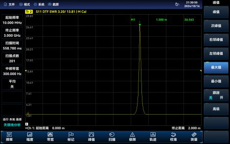
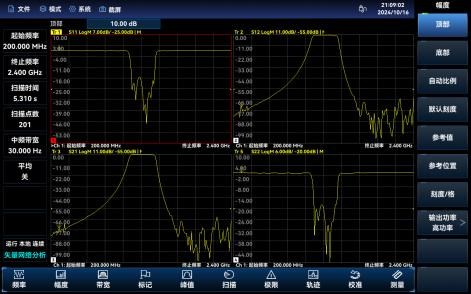
Antenna feeder analysis (option)
The antenna feeder analysis of the S5109 microwave analyzer can measure the echo loss, voltage standing wave ratio, impedance, cable loss and fault point distance of cables and feeders. The echo loss and fault point distance measurement will help you determine the specific reasons for the decrease of system performance in the antenna feeder system. The day feeder analysis function supports the TDR test, which can analyze the type of cable failure. In addition, the instrument is also built-in some com monly used cables, feeder parameters, easy to use.
-
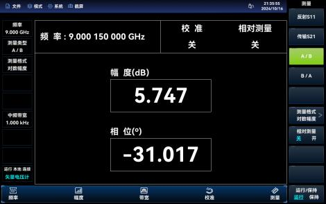
Vector voltage meter (option)
The vector voltmeter of S5109 microwave analyzer can match the electrical length and phase shift of the measured device, support A / B and B / A measurement functions, and can measure the amplitude phase consistency of the receiver.
-
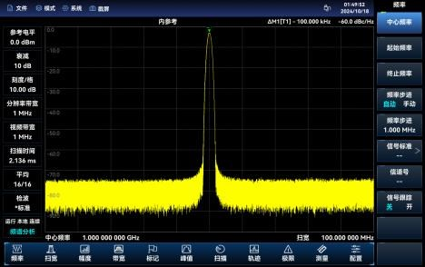
Spectrum analysis
S5109 microwave analyzer has standard channel power, occupied bandwidth, adjacent power, spectrum transmission template, load-to-noise ratio, audio demodulation, harmonic distortion, spectrum transmission template, carrier adjacent power, third order adjustable test function, with high sensitivity, scanning speed, large dynamic range, good phase noise index, etc. S5109 microwave analyzer built-in a variety of predefined signal standard can be directly called, support noise marker and frequency counter function, can display three traces at the same time, and has the standard, positive peak, negative peak, sampling, mean and root rms different inspection mode, support signal tracking and peak tracking function, has the function of peak list.
-
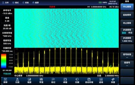
Interference analysis (option)
The interference analysis option has the function of spectrum measurement, waterfall map and RSSI measurement, where the waterfall map uses frequency-amplitude-time three-dimensional display, which can easily observe periodic or intermittent signals, and display the strength of the response signal amplitude of different colors in the waterfall map.RSSI (received signal intensity indication) is mainly used to measure the intensity change of a point frequency signal in a period of time, and the waterfall map and RSSI measurement support the signal automatic storage function.
-
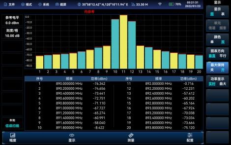
Channel Scan (option)
The channel scan measurement mode provides a measurement of the signal power of the multiple channels. The signal power is displayed in the form of a bar chart or as a list, measuring the signal power of up to 20 channels. According to the way of channel setting channels, there are three measurement methods: channel scanning, frequency scanning and list scanning. The three measurement methods can set the bandwidth and the number of channels.
-
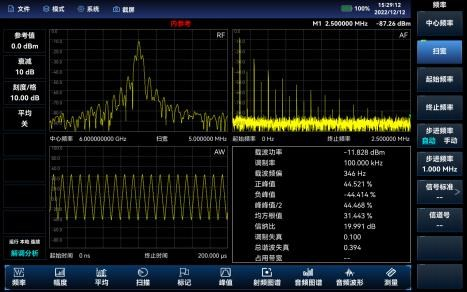
Analog demodulation analysis (option)
Demodulation analysis measurement mode provides display of the AM, FM, PM modulated signal atlas and analysis of related parameters. The main maps and associated parameters are measured as follows:
RF spectrum: similar to the spectrum analysis mode, showing the spectrum of the modulation signal, can measure the bandwidth. Audio atlas: a spectrum of the audio demodulated signal.
Audio waveform: displays the waveform of the audio signal in time domain.
Parameter analysis: the carrier power, modulation rate, carrier frequency bias, modulation depth (AM), modulation frequency bias (FM), modulation phase bias (PM), signal-a-nore ratio, modulation distortion, total harmonic distortion and other parameters can be measured and analyzed.
-
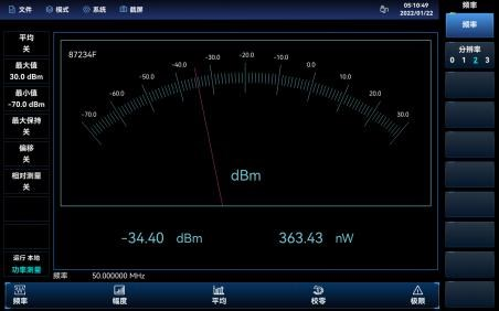
USB power measurement (option)
The USB power measurement function can measure CW signal power of up to 40GHz through the external Saluki S8723X series external USB power sensor.
-
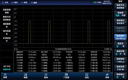
USB peak power measurement (option)
The S87234 USB peak power sensor can test RF / microwave signals of up to 67GHz to achieve pulse power measurement in a large dynamic range.
-
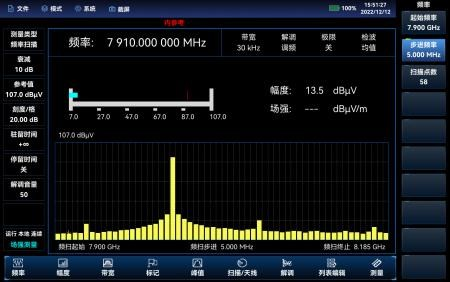
Field strength measurement (option)
The S5109 microwave analyzer and portable antenna can conduct field strength measurement for space electromagnetic environment monitoring and radio management. Support for users to directly call antenna files or custom antenna factors. Field strength measurement can be divided into three modes: point frequency measurement, frequency scan measurement and list scan measurement. The point frequency measurement observes the frequency bias, amplitude value and field strength value of the current point by setting the point frequency rate, observes the amplitude value and field strength value within a frequency range by setting the starting frequency, step frequency and the amplitude value and field strength value of the list frequency point by calling a pre-edited or saved list.
-
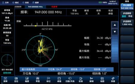
Directional analysis (option)
The directional analysis options should be equipped with directional antenna, electronic compass and GPS / Beidou options to realize the functions of direct interference signal search, horizontal scanning direction measurement and map cross-positioning. When selected with the SZE9080 series antenna and handheld handle, it is not necessary to be configured separately because of its built-in electronic compass.
-
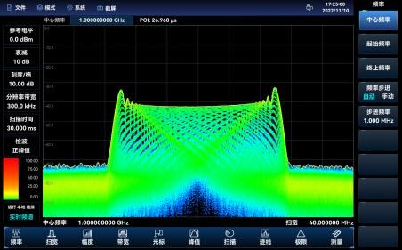
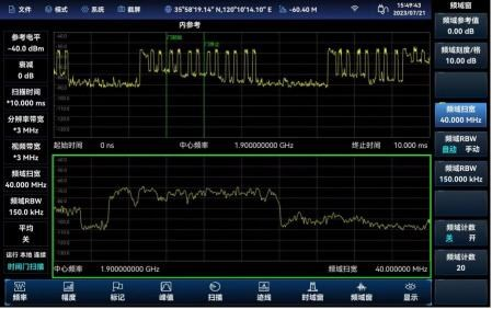
Real-time spectrum analysis (option)
The real-time spectrum analysis function is mainly used for the capture and analysis of transient time-varying signals and burst signals. The real-time analysis bandwidth supports 40 MHz, which can realize the measurement function of transient signal digital afterglow and waterfall map.
-
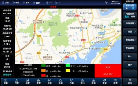
Outdoor map (option)
Outdoor map option is a measurement function in spectrum analysis mode, which can do the RSSI test of interference signal and the adjacent channel power ratio test, and the test results can be marked on the map in real time according to the time or distance. The test results marked on the map can be saved to the instrument for subsequent calls.
-
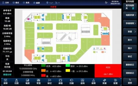
Indoor map (option)
The indoor map option can do RSSI test and adjacent channel power ratio test. Because the GPS signal cannot be received indoors, the user needs to manually move the position and mark the test results on the map. The test results marked on the map can be saved to the instrument to facilitate the later call to view. Users can store the plan in picture format into tile diagram to the instrument through special software (along with the selection).
-
Time gate function (option)
Time gate scanning function is used to screen for the time division signal, the time gate scanning function is divided into time domain window and frequency domain window, time domain window can select the frequency domain results will be displayed in the frequency domain window, time gate scanning mode is zero sweep wide state, with various parameter setting can be set from the domain, the uplink frames and downlink frames in the TDD signal are distinguished. By setting [gate delay] and [gate width], the uplink signal can be selected to achieve the effect of “filtering” the downlink signal (the downlink signal will affect the interference signal search).
-
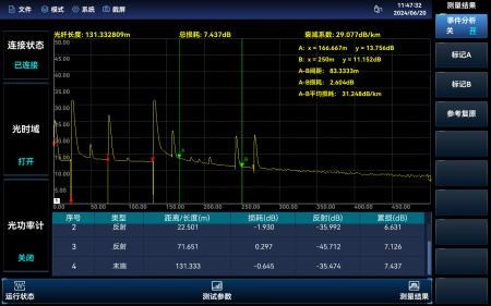
OTDR (option)
The optical time domain reflector function of S5109 microwave analyzer can realize the external USB optical time domain reflector, and can realize optical power measurement.
| Spectrum Analysis Nominal Frequency | 10MHz |
| Aging Rate | ±0.5ppm/year |
| Temperature Stability | ±0.1ppm (-2 0℃ – + 55℃, relative to 25℃±10℃) |
| Accuracy Of Frequency Readout | ± (frequency reading x frequency reference accuracy + 1% x sweep width + 10% x resolution bandwidth) |
| Sweep Width | Range: 0Hz (zero sweep width), 10Hz- corresponding to the upper limit of the model frequency range Accuracy: ±1.0% |
| Sweep Time | Range: 1μs to 6000s (zero sweep width) Accuracy: ±1.0% (zero sweep width) |
| Resolution Bandwidth | Bandwidth range: 1Hz-20MHz (1-2-3-5-8 steps) |
| Sideband Noise | ≤-108dBc/Hz@10kHz; ≤-110dBc/Hz@100kHz; ≤-118dBc/Hz@1MHz; ≤-129dBc/Hz@10MHz |
| Vector Network Analysis Frequency Accuracy | ±0.9ppm |
| Frequency Resolution | 1Hz |
| Power Rating | Set the power high, low or manually |
| Port Output Power | high power: ≥-8.0dBm (300kHz≤f≤10MHz) ≥3.0dBm (10MHz<f≤9GHz) ≥0.0dBm (9GHz<f≤20GHz) ≥-2.0dBm (20GHz<f≤26.5GHz) ≥-8.0dBm (26.5GHz<f≤44GHz) ≥-8.0dBm (44GHz<f≤50GHz) ≥-12.0dBm (50GHz<f≤54GHz) low power: ≤-35dBm (10MHz≤f≤54GHz) |
| Port Output Power Accuracy | Note: -10dBm output, 23±5℃ ±2.0dB (300kHz≤f≤26.5GHz); ±2.5dB (26.5GHz<f≤50GHz); ±3.0dB (50GHz<f≤54GHz) |
| Effective Directivity | ≥42dB (300kHz≤f≤4GHz); ≥34dB (4GHz<f≤20GHz); ≥26dB (20GHz<f≤54GHz) |
| Dimension | 316.5mm (wide) x 236.5mm (high) x 75mm (deep) (excluding side handle, panel connector and interface plug, closed rear bracket) |
| Weight | S5109B/D: ≤3.7kg (without built-in battery) S5109E/G/H/K: ≤3.9kg (without built-in battery) |
| Power Input Form | Alternating current power adapter: input voltage 100V to 240V AC,50Hz/60Hz Output voltage 19V DC, 4.7A Built-in lithium ion battery: nominal voltage 10.8V |
| Battery Life | Typical value 3h |
| Test Port | S5109B/D: N-type male S5109E: 3.5mm male S5109G/H: 2.4mm male S5109K: 1.85mm male |
(Note: see more detail information in the ‘Resource’ – ‘Datasheet’) |
Main Machine
| Module No. | Item | Description |
| S5109B | Microwave Analyzer | 9kHz /300kHz-9GHz (SA/VNA) |
| S5109D | Microwave Analyzer | 9kHz /300kHz-18GHz (SA/VNA) |
| S5109E | Microwave Analyzer | 9kHz /300kHz-26.5GHz (SA/VNA) |
| S5109G | Microwave Analyzer | 9kHz /300kHz-44GHz (SA/VNA) |
| S5109H | Microwave Analyzer | 9kHz /300kHz-50GHz (SA/VNA) |
| S5109K | Microwave Analyzer | 9kHz /300kHz-54GHz (SA/VNA) |
Options
| Module No. | Description | Function and performance |
| S5109-01 | English option | Includes English signs, menus and quick use guides. |
| S5109-03 | English user manual | English version of user manual. |
| S5109-05 | Programming Manual in English | Programming Manual in English. |
| S5109-S01 | USB CW power measurement | Power measurement function is provided and should be used with external USB continuous wave power probe S87230/S87231 /S87232/S87233. |
| S5109-S02 | USB peak power measurement | Provides peak power measurement function, which needs to be combined. The S87234D/E/F/LUSB peak/average power meter is used. |
| S5109-S03 | Interference analysis | Provides waterfall charts, RSSI measurements, and more. |
| S5109-S04 | Channel scanning | Provides signal power measurements for multiple channels. |
| S5109-S05 | Field strength measurement | Used for measuring the electric field radiation intensity of the measured equipment |
| S5109-S06 | Outdoor map | The RSSI test and adjacent channel power ratio test can be performed under the outdoor interference map, and the test results can be marked on the map in real time according to time or distance. It should be used with S5109-H01 option. |
| S5109-S07 | Indoor map | RSSI and adjacent channel power ratio tests can be performed under the indoor map, and the test results can be correlated with color through signal strength |
| S5109-S08 | Analog demodulation analysis | It can realize the analysis and measurement function of AM, FM and PM modulation signals. |
| S5109-S09 | Zero span IF output | When the zero sweep width is wide, the output analog intermediate frequency signal is generated. |
| S5109-S10 | Time gate function | Used for time division interference signal test, air interface wireless signal test needs to be used in conjunction with S5109-H01 option. |
| S5109-S11 | Directional analysis | For locating external interference sources or unknown signals, it should be used in conjunction with S5109-H0 1 option, USB electronic compass option and directiona I antenna option. |
| S5109-S12 | Real-time spectrum analysis with 40MHz bandwidth | Provides real-time spectrum analysis with 40MHz bandwidth. |
| S5109-S13 | List sweep | Continuous scanning measurement of multiple frequency bands is realized |
| S5109-S14 | IQ analysis | Achieve the capture and display function of IQ data. |
| S5109-S18 | Vector signal analysis | It has a variety of single carrier digital modulation signal demodulation and analysis functions, which can provide spectrum diagram, vector diagram, constellation diagram, eye diagram, error/symbol table and other display Windows to analyze the characteristics of modulation signals. |
| S5109-S19 | EMI analysis | Support EMI scanning, point frequency scanning and list scanning functions, with CISPR average, CISPR effective value and quasi peak detection mode. |
| S5109-S20 | Phase noise measurement | Provide single sideband phase noise curve and single point phase noise test. |
| S5109-S30 | Antenna feeder analysis | Used for cable, feeder and other echo loss, standing wave ratio, breakpoint testing. |
| S5109-S31 | Vector voltmeter | Used for cable phase shift and electrical length test. |
| S5109-S32 | TDR | Used to analyze the fault nature of cable fault point ocation. |
| S5109-S33 | Electronic calibration kit support | Software options require additional electronic calibration components for vector network analysis, antenna feeder analysis, vector voltmeter calibration,etc. |
| S5109-S34 | OTDR | Provides optical time domain reflectometer and optical power meter functions. |
| S5109-S35 | Mixed S parameters | Used for differential S parameter measurement. |
| S5109-S36 | VNA time domain measurement | Used for vector network analysis mode time domain measurement |
| (Note: see more detail information in the ‘Resource’ – ‘Datasheet’) |


