
Saluki S3503 signal/spectrum analyzer is featured with wide frequency range (up to 67GHz), excellent dynamic range, low phase noise, precision amplitude and high testing speeds. S3503 signal/spectrum analyzer is available for using programming commands.
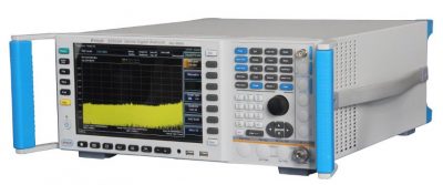
Fig.1 S3503 Signal/Spectrum Analyzer
This section briefly introduces the demodulation test of IEEE802.11a/g signal in the wireless communication signal test application of S3503 signal/spectrum analyzer.
1. Fundamental
The IEEE802.11a/g standard signal is transmitted by a packet protocol data unit (PPDU), and one PPDU is a pulse. The PPDU frame format internally contains a plurality of information such as a modulation mode and a transmission rate of the transmission signal. PPDU frame structure is shown in Fig.1.
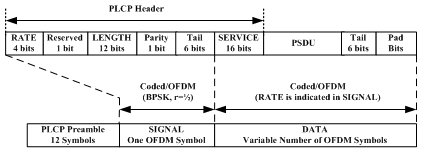
Fig.1 IEEE802.11a frame structure
The structure of the PPDU includes a PLCP (Physical Layer Convergence Procedure) preamble, a PLCP header, a PSDU (Physical Sub-layer Data Unit), a tail bit, and a zero padding. PLCP preamble: used for signal detection, frequency offset estimation, channel estimation, etc., consisting of 10 short training symbols and 2 long training symbols.
The demodulation test mainly analyzes the PCLP header by processing the captured PPDU pulse through synchronization, channel estimation, etc. according to the IEEE802.11a/g signal frame structure, and obtains a series of modulation parameters such as the length of the data and the modulation mode, and then obtains a series of modulation parameters. The modulation parameters realize the demodulation of the data segment, and finally the error signal is calculated by using the demodulated measurement signal and the reference signal.
2. Key Features
(1) Rich display function: including time domain search view, time domain waveform view, constellation diagram, spectrogram, error vector spectrum, gain imbalance vs. carrier, quadrature error vs. carrier, error table, symbol table Wait for 9 views;
(2) One-button automatic test or manually set by the user: its subcarrier spacing, guard interval, symbol timing adjustment, demodulation type, synchronization mode, equalization training mode, Evm threshold, frequency offset threshold, etc. Can be manually modified by the user;
(3) The error table provides a wealth of error parameter calculation results: including Rms Evm, Peak Evm, pilot Evm, data domain Evm, frequency error, origin offset, quadrature error, gain imbalance, average burst power, peak burst The error parameters such as power generation and power peak-to-average ratio are displayed, and the modulation parameters such as the debug mode, transmission rate, number of symbols, and coding efficiency are displayed.
3. Measurement Steps
(1) Enter the IEEE802.11a demodulation test function interface, select [Mode], [WLAN Signal Analysis], and enter the WLAN signal analysis interface. Then select the test standard, select [Measure], [802.11a/g], select the IEEE802.11a/g standard, and measure the function selection [modulation accuracy test].
(2) The transmission of the IEEE 802.11a/g signal is in the form of a pulse, so its demodulation test is first the capture of its PPDU pulse. Select [Measurement Settings], [Measurement Time], then [Search Length] to set the appropriate value. Select [Time Domain Search] window from [Display] and [Window Type] to observe the time domain search window. The time domain search length must be ensured. More than one full PPDU pulse. The time domain search view is shown in Fig.2.
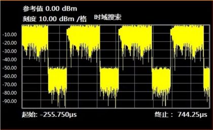
Fig.2 Time domain search view
(3) The remaining settings can be automatically demodulated with the default settings. The view is as shown in Fig.3.
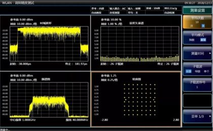
Fig.3 Automatically demodulated setting view
(4) Select [Measurement Settings] and [Measurement Time]. By setting [Measurement Interval], [Measurement Offset], [Analysis Length], etc., you can perform timing analysis on PPDU pulses.
(5) Select [Measurement Settings] and [Advanced Settings]. By setting [Symbol Timing Adjustment], you can adjust the OFDM symbol demodulation start position to avoid inter-symbol interference between OFDM symbols.
(6) Select [Measurement Settings], [Advanced Settings], [Pilot Tracking] to set [Amplitude Tracking], [Phase Tracking], and [Timing Tracking]. Since the equalizer is not ideal enough to change with the increase of the PPDU pulse length, the demodulation effect can be improved by correcting the data subcarrier signal by amplitude tracking, phase tracking and timing tracking of the pilot signal.
(7) Select [Measurement Settings], [Advanced Settings], [Equalization Training], and you can select [Synchronized Training Sequence] or [Synchronized Training Sequence & Data] for equalization. Synchronous training sequence & data equalization can obtain more accurate channel estimation, but the processing method is more complicated. The default equalization mode is synchronous training sequence equalization.
(8) Select [Measurement Settings], [Subcarrier] menu, you can select [All], [Pilot], [Single] three subcarrier selection analysis modes, select [All] to analyze all subcarriers, select [Guide] The frequency] only analyzes the pilot subcarriers, and selects [single] to analyze the selected single subcarriers.
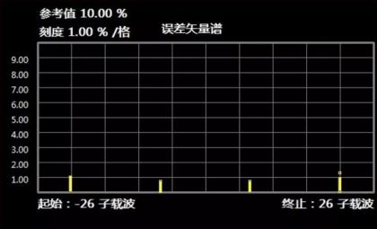
Fig.4 Subcarrier selection analysis
(9) Select [Display], [Window Type], you can switch between different windows, select [Quadrature Error vs. Subcarrier], [Gain Unbalance vs. Subcarrier], which can achieve orthogonality on each subcarrier. Error and gain imbalance are analyzed.
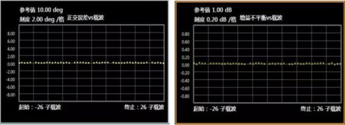
Fig.5 Quadrature error and gain imbalance analysis
(10) Select [Display], [Window Type], select [Error Table], [Symbol Table] to observe the modulation error parameters and demodulation code stream.
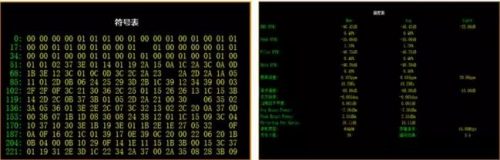
Fig.6 Symbol table and error parameter table
