
The concepts of distortion and noise in signal processing overlap to a limited extent, but they are distinct phenomena. Distortion in a signal is the alteration or change of the shape or some other characteristic of the waveform. In contrast, noise is an external random signal added to the original signal. It’s harder to remove the effects of noise than to remove the effects of distortion. Noise also has a more stochastic nature compared to distortion.
A typical electronic signal that is free of distortion consists of a transfer function in which the output y(t) is a function only of the input x: y(t) = F(x)(t). Distortion is present when any of these conditions are present:
F is a nonlinear function. Phase-locked loops, detectors, and mixers are all nonlinear circuits. Mathematically, a nonlinear filter outputs signals R and S for two input signals r and s separately, but does not always output αR + βS when the input is a linear combination αr + βs.
Ordinary high-pass and low-pass filters can also cause distortion. A high-pass filter can distort the shape of a square wave by removing some or all of the low-frequency components. A low-pass filter can round the square-wave corners by removing the high-frequency components.
A tube-type amplifier can be moderately non-linear, slightly compressing the peak of a sine wave. Small amounts of low-order harmonics are generated. A clipping transfer function generates higher-order harmonics. Those parts of the transfer function that are flat indicate a total loss of input signal information during the flat intervals. This is an instance of severe distortion.
Amplitude distortion arises when the output amplitude is not a linear function of the input amplitude.
Harmonic distortion contributes overtones, which consist of integer-numbered multiples of the fundamental. In the case of a pure sine wave input, often the system generates non-linearities which appear in the output. Audio engineers and system designers measure this energy as total harmonic distortion (THD) or alternately, THD plus noise, usually the more relevant metric.
To be precise, THD is defined as the ratio of the sum of the powers of all harmonic components to the power of the fundamental frequency. Lower distortion is highly desirable in audio systems because speakers, amplifiers, microphones or other non-linear equipment produce a more accurate reproduction of on-stage or in-studio events. In radio communication, harmonic distortion widens the frequency spectrum at the output, thus high-THD devices perform poorly in spectrum sharing and sensing.
In power systems, high THD equates to higher peak currents, heating, electromagnetic emissions and core loss in electric motors. Best practices and requirements for harmonic control in electric power systems may be found in IEEE std 519–2014.
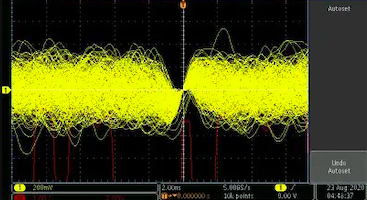
Noise displayed in an oscilloscope. Notice that because it is a logarithmic function, it goes to zero at the axis.
Noise is distinguished from distortion in that it is added to the signal of interest. The classic example is thermal or Johnson-Nyquist noise. Any device, component or conductor generates thermal noise unless it is cooled close to 0°K. This Johnson-Nyquist noise is unavoidable. It arises from the random thermal motion of electrons or other internal charge carriers and arises even with no applied voltage. Its spectral density is equal throughout the frequency spectrum so it is considered white noise.
Frequency display instruments such as spectrum analyzers show a distinctive irregular fluctuating trace near the bottom of their screen. This is known as the noise floor and is random subatomic motion. No signal can be detected below that noise floor, so instrument builders constantly try to lower that noise floor to improve sensitivity to faint signals.
Shot noise is the result of random fluctuations of electrical current when the electrons traverse a potential barrier (voltage differential). The classic example is a PN junction diode. Shot noise is produced when the electrons and holes cross the barrier, shot noise is produced. More specifically, shot noise originates from the discrete nature of electric charge–charge carriers exhibit discrete arrival times. In audio, the shot noise resembles raindrops falling on a steel roof. On a macro scale, the rain is constant, but the individual raindrops are discrete events.
Vacuum tubes also exhibit shot noise because the electrons strike the anode in a random-discrete fashion. The phenomenon is not as pronounced in a vacuum tube as in semiconductors, however, because of a space charge, which moderates the effect. Shot noise is not exhibited in conductors and resistors because of the smooth motion of the charge carriers, which evens out their arrival times.
There are several other types of noise of interest in electronics. Partition noise happens when current divides between at least two paths. It arises because of random fluctuations in the division. At audio frequencies, it sounds just about like shot noise. Flicker noise, also known as 1/f noise, is characterized by a frequency spectrum that declines steadily as frequency rises. It is also known as pink noise. Because it declines with rising frequency, it generally isn’t much of an issue above about 500 Hz. Burst noise– also dubbed popcorn noise, impulse noise, bi-stable noise, or random telegraph signal (RTS) noise–consists of sudden step-like transitions between two or more discrete voltage or current levels and happens at random and unpredictable times. In audio reproduction, the sound resembles popcorn kernels bursting at irregular intervals. There’s no single source of burst noise but the most common cause is the random trapping and release of charge carriers at thin film interfaces or at defect sites in bulk semiconductor crystal. Transit-time noise resembles shot noise and becomes more pronounced in smaller components due to the quantized nature of electricity. Transit-time noise results when a signal frequency’s period is the same as the travel time of an electron going from sender to receiver. As device dimensions approach the length of a wavelength at higher frequencies, transit time amplitude rises, obscuring other types of noise.
There are a few other noise sources that sometimes arise. Reactive coupling introduces noise from outside the circuit via reactive elements (capacitors and inductors), for example through a receiving antenna. Intermodulation noise is a bit of a misnomer. It actually refers to the spurious frequency components generated when two or more signals pass through a non-linear device. Thus these are intermodulation products which contain both sum and difference products of the frequencies involved. This actually distortion rather than electronic noise in the strict sense because it doesn’t arise from outside the system.
The original article website:
