
SE Series Lock-in Amplifier Input Methods and Signal Acquisition Modes |
Proper input configuration directly determines the measurement accuracy and noise immunity of a lock-in amplifier. This article explains the input port design, signal acquisition modes, and coupling options of the SE series lock-in amplifier.
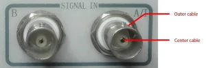
Figure 1. Appearance of the signal input ports on the SE series.
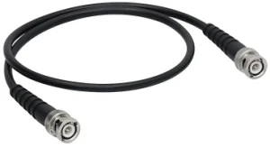
Figure 2. BNC-to-BNC cable
1. BNC Input Port and Connection Design |
The SE series lock-in amplifier uses a BNC female connector (Bayonet Nut Connector) as its signal input port. When paired with a matching BNC-to-BNC coaxial cable, it forms a reliable signal path from the signal source through the coaxial cable to the lock-in amplifier input.
This connection design improves measurement reliability by minimizing system noise:
- It reduces interference from external noise sources such as motors and signal generators
- It resolves differential ground issues between the detection probe and the lock-in amplifier
2. Voltage Signal Acquisition Modes |
The SE series lock-in amplifier supports two voltage acquisition modes: single-ended input for convenient wiring, and differential input for reduced noise pickup.
2.1 Single-Ended Input (Mode A) |
In single-ended input mode, the center conductor of the coaxial cable acts as the signal line, and the outer shield serves as the ground line.
The lock-in amplifier only detects input port A, taking the potential difference between the center conductor and outer shield as the input signal. Instead of directly grounding the outer shield, the instrument connects it to internal ground through a user-selectable resistor: 10 kΩ for the Float option, 10 Ω for the Ground option.
This series resistor eliminates ground loop issues caused by ground potential differences between the test setup and the lock-in amplifier. Its limitation is that it cannot suppress noise picked up by the outer cable shield.
2.2 Differential Input (Mode A-B) |
In differential input mode, both signal paths use the center conductors of two coaxial cables.
The lock-in amplifier measures the voltage difference between the center conductors of port A and port B as the input signal. The outer cable shields pick up environmental noise but do not participate in signal acquisition, acting as a protective barrier against noise interference for the center conductors.
When using differential input mode, keep the two signal cables equal in length and routed close to each other to avoid false signal pickup from electromagnetic induction.
3. Current Signal Acquisition (Mode I) |
In current input mode, the signal is transmitted through the center conductor of input port A.
The instrument converts the current signal into a voltage signal with selectable gain of 10⁶ or 10⁸. Current input mode is recommended for high-impedance signal sources (>1 MΩ) with small output currents.
This mode features low input impedance and minimal cable capacitance effect, which reduces amplitude and phase errors during measurement, and lowers high-frequency noise gain of the current-range pre-amplifier.
4. AC Coupling vs DC Coupling |
In addition to input mode selection, users need to choose between AC coupling and DC coupling for signal input.
4.1 AC Coupling |
AC coupling passes the signal through a high-pass filter with a 200 Hz cutoff frequency to remove low-frequency noise and DC offset.
Unfiltered DC components will produce erroneous output at the reference frequency, and subsequent low-pass filter processing will increase the system measurement response time.
4.2 DC Coupling |
DC coupling feeds the signal directly into the instrument without the high-pass filter. DC coupling should be selected when the signal frequency is below 200 Hz to ensure accurate amplitude measurement.
Related products: |
Lock-In Amplifiers: Principle, Applications & Products | Saluki Technology
♦ Need technical support or a custom solution? Contact our application engineers: saluki@salukitec.com.
♦ To request a quotation, please contact sales@salukitec.com or click “Contact Us“ to leave a message.
