
Saluki S3302 series handheld spectrum analyzer has a variety of measurement functions. One of the measurement methods is noise signal measurement. This section we will continue to introduce this measurement (Part I).
Noise Measurement by Noise Marker Function
In this example, the noise of 1Hz bandwidth is measured by the noise marker function, using the 1GHz external signal.
a) Set the output signal of the signal generator:
Set the frequency of the signal generator as 1GHz and power as -10dBm. Connect the output of the signal generator to the input port of the spectrum analyzer, and enable the ON state of the radio frequency.
b) Set the center frequency, span, reference level and attenuator:
Press [Reset].
Press [Frequency], [Center Frequency], 999.98[MHz]
Press [frequency], [Span] and 100[kHz].
Press [Amplitude], [Ref Level] and -10[dBm].
Press [Amplitude], [Atten Auto Man] and 40[dB].
c) Activate the noise marker:
Press [Maker] and [Noise Marker Off On].
Note: The “Sample” mode of the detector will be enabled automatically. To obtain the noise power under different bandwidth, you can correct the current bandwidth based on 10×log(BW). For example, if the noise power within 1 kHz bandwidth is to be obtained, 10×log (1000) or 30 dB has to be added to the reading.
d) Reduce the measurement error by increasing the sweep time:
Press [Sweep], [Sweep Time Auto Man] and 3[s].
In the “Average” mode of the detector, you can increase the sweep time so that the trace data are averaged in a longer interval, so as to reduce the measurement error.
e) Move the marker to 1GHz:
Press [Maker] and rotate the knob on the front panel until the noise marker reading is 1GHz.
The noise marker value is calculated based on 5% of points on the whole sweep trace, with the marker location as the center. The noise marker will not be at the signal peak since such position has no enough trace points for calculation. Therefore, when the resolution bandwidth is narrow, the noise level will average trace points below the signal peak. As shown in Fig.1:
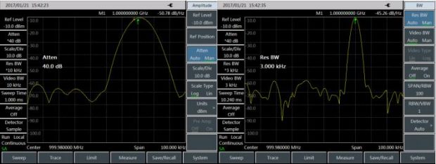
Fig. 1 Noise Measurement by Noise Marker Function
f) Set the spectrum analyzer into the zero span mode, with the marker location as the center:
Press [Peak] and [Marker→Center].
Press [frequency], [Span] and [Zero Span].
Read the [Maker].
In this case, the amplitude reading of the noise marker is correct, as the averages of all points are at the same frequency, which is not affected by the shape of the resolution bandwidth filter. The noise marker is calculated based on the average of the interested frequency points. The power of discrete frequency points should be measured in the zero span mode, with the spectrum analyzer tuned to the interested frequency point.
