
Based on the fabrication of two-dimensional elliptical ultrasonic vibrators and the application of vibration characteristics testing, the purpose of our research using power amplifiers is to detect and verify whether the actual resonance frequency of the manufactured piezoelectric ceramic vibrator is the same as the design.
By dividing the electrodes on a large piece of piezoelectric ceramics, it actually has the effect of arranging four piezoelectric ceramics side by side. The material of the electrodes is Ag. The power amplifier drives the piezoelectric ceramics to be plated on the surface of the piezoelectric ceramics through the method of coating. Electroceramics and 304 stainless steel substrates are bonded by epoxy resin to realize vibration transmission.
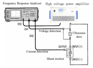
The circuit diagram used for resonance characteristic analysis is shown in the figure. The frequency characteristic analyzer provides the output signal of frequency sweep, and can measure the voltage across the piezoelectric ceramic vibrator and the current passing through the piezoelectric ceramic vibrator. Power amplifier (SLA-HVP-437) The input signal is amplified and added to the vibrator circuit, and the piezoelectric ceramic vibrator is connected in series with a standard resistance of one ohm. The frequency sweep range is 20k—30kHz. Among them, when only two spaced electrodes are energized, the B4 mode of the vibrator is excited, and when the four electrodes are energized at the same time, the L1 mode of the vibrator is excited.
1. It can be seen from the figure that the resonant frequency of the B4 mode of the vibrator is 24.10kHz, the anti-resonant frequency is 24.22kHz, the resonant frequency of the L1 mode is 24.01kHz, and the anti-resonant frequency is 24.24kHz. The difference between the resonant frequencies of the two vibration modes is about 0.09 kHz, and this level of error is within the allowable range when using this ultrasonic vibrator. Furthermore, since the resonance frequency difference between the two oscillation modes is small, the maximum amplitude can be obtained at the same frequency for both longitudinal and bending vibrations, at which point the amplitude of the synthesized elliptical vibrations will be maximum. On the other hand, the difference between the anti-resonance points in the two vibration modes is about 0.02kHz, which is very small. Because when the ultrasonic vibrator is excited at the resonance point, although the impedance is small, and the amplitude is the largest. However, if a frequency close to the resonance point is used, a relatively large load is applied to the piezoceramic, which may cause cracking or cracking of the piezoceramic material. Whereas when excited at the anti-resonance point, impedance increases, and power dissipation is minimized. Therefore, the frequency of the excitation signal is usually at the anti-resonance point, and a difference of 0.02kHz is acceptable. Therefore, it can be seen that the vibrator shown in the figure will produce an optimal ultrasonic elliptical trajectory when excited at a frequency of 24.22kHz.
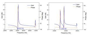
Impedance characteristic curve for L1 mode Impedance characteristic curve for B4 mode
2. When the vibrator is excited at a frequency of 24.22kHz, it will produce the best ultrasonic elliptical trajectory.
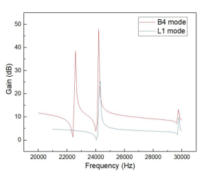
Impedance characteristics of L1 mode and B4 mode
Obviously, the SLA-HVP-437 high-voltage power amplifier can drive piezoelectric ceramics to ensure that the ultrasonic wave can output a complete sine wave, and can freely adjust the gain range, so that it can freely switch the strength of the ultrasonic signal under different light intensities. achieve the purpose of the experiment.
