
Noise Sources in Lock-in Amplifiers: Internal Noise & External Interference |
The basic function of a lock-in amplifier is to extract target signals from noisy environments, and noise exists in all electronic systems. By origin, noise falls into two categories: internal intrinsic noise and external environmental noise.
At the microscopic level, internal noise comes from the random instantaneous motion of charge carriers, which makes instantaneous values unpredictable. External noise is caused by unpredictable interference from the outside environment, which triggers internal system responses and measurement errors. Subjectively, any unwanted signal that hinders accurate measurement can be regarded as noise. Although noise has unpredictable instantaneous values, it follows certain statistical rules instead of being completely chaotic.
I. Common Internal Noise Sources in Electronic Systems |
1. Thermal Noise (Johnson Noise) |
Thermal noise exists in all electronic systems, even when the system is not powered on. First discovered by J.B. Johnson in 1928, it is also called Johnson noise.
The RMS noise voltage is calculated as:
Vnoise (rms)=(4kTRΔf)1/2
Where k = Boltzmann constant (1.38×10⁻²³J/K), T = Kelvin temperature, R = resistance (Ω), Δf = measurement bandwidth.
Thermal noise has a frequency-independent power spectral density, which means it is a type of white noise.
2. Shot Noise |
Shot noise mainly exists in PN junctions, caused by random emission and annihilation of charge carriers that lead to current fluctuation across the potential barrier. First discovered by W. Schottky in 1918, it is proven to be white noise.
The RMS noise current is calculated as:
Inoise (rms)=(2qIΔf)1/2
Where q = elementary charge (1.62×10⁻¹⁹C), I = average DC current or RMS AC current of the PN junction, Δf = measurement bandwidth.
Its impact is negligible in narrowband measurement systems.
3. 1/f Noise |
First discovered in electron tube currents in 1925, 1/f noise arises from random fluctuations of contact resistance at imperfect conductor contacts.
Its core feature is that power spectral density is inversely proportional to operating frequency f — the lower the frequency, the stronger the noise impact. The power spectral density function is:
Inoise (rms)=(2qI△f)1/2
Where K is a constant related to material, contact condition and geometry, Id = average DC current, f = operating frequency.
Carbon resistors have typical 1/f noise of 0.1–0.3 μVrms; metal film or wire-wound resistors have roughly one order of magnitude lower noise.
4. Total Internal Noise |
The internal noise sources mentioned above are independent of each other. The total internal noise RMS value is obtained by squaring each noise RMS value, summing them up, and taking the square root.
II. External Noise Sources |
Besides internal noise, various environmental interferences exist in experiments. Most external noise is asynchronous with the system reference signal and uncorrelated in frequency domain, coming from lighting, motors, radios, monitors and other devices.
Some external noise is synchronous and correlated with the target signal, which will cause severe signal distortion and cannot be eliminated by frequency-based methods — the lock-in amplifier will recognize this noise as the target signal. A typical source is ground current issues in the experimental setup.
External noise can couple into the signal path in multiple ways.
1. Capacitive Coupling |
A nearby AC voltage source can couple into the measurement path through stray capacitance. Even tiny stray capacitance can produce noise much larger than the weak target signal, especially when the noise is synchronous with the target signal. High-frequency noise sources have more obvious coupling effects.
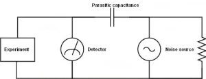
The noise current can be estimated as:
i=Cstray dt/dV=ωCstray Vnoise
Where ω = angular frequency, Vnoise = noise amplitude, Cstray = stray capacitance.
Optimization methods: |
- Turn off or remove identifiable noise sources
- Keep noise sources away from the measurement path to reduce stray capacitance
- Measure voltage across small impedance devices instead of direct current measurement when noise cannot be removed
- Enclose the signal source and detector in a metal shield
2. Inductive Coupling |
A nearby AC current source can couple into the measurement loop through magnetic field. Fluctuating current causes magnetic field changes, which alter the magnetic flux of the measurement loop, similar to transformer coupling.
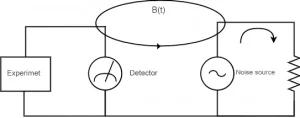
Optimization methods: |
- Turn off or remove identifiable noise sources
- Use twisted-pair or coaxial cables to reduce loop area; twist coaxial cables for differential connections
- Use high-impedance detectors for current measurement instead of voltage measurement when noise cannot be removed
- Add magnetic shielding to block alternating magnetic fields
3. Resistive Coupling & Ground Current |
Resistive coupling (ground current effect) refers to the potential difference generated by ground current between the current injection point and the remote working ground. When the noise source is connected across the system ground and the detector ground, the ground current will cause measurement errors.
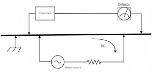
Optimization methods: |
- Connect all component ground references to the same physical point (single-point grounding)
- Use thick enough ground wires to reduce resistive effect
- Avoid large current grounding near small-signal circuits
4. Microphonic Effect |
Mechanical vibration can also introduce noise into electronic systems. For example, vibration of connecting cables will change their capacitance, affecting the signal current and causing measurement errors.
According to the capacitance formula
Q=CV
the current is:
I=dQ/dt=C dV/dt+V dC/dt
Vibration changes the dC/dt term and affects the cable current.
Optimization methods: |
- Eliminate mechanical vibration around sensitive signal cables
- Use low-noise cables to reduce the impact
5. Thermocouple Effect |
When different metals form a loop with two junctions at different temperatures, a thermoelectromotive force will be generated. This effect causes slow-varying interference in microvolt-level voltage measurements, especially prominent at low frequencies (mHz range).
Optimization methods: |
- Keep the temperature of the measurement environment and detector stable
- Apply cold junction compensation with an opposite-polarity thermocouple at the same temperature
Related products: |
Lock-In Amplifiers: Principle, Applications & Products | Saluki Technology
♦ Need technical support or a custom solution? Contact our application engineers: saluki@salukitec.com.
♦ To request a quotation, please contact sales@salukitec.com or click “Contact Us“ to leave a message.
