
Saluki S3302 series handheld spectrum analyzer has the advantages of broad operating band, high performance indicators, high sweeping speed, multiple test functions, easy operation, etc. From the perspective of performance indicators, this instrument has low average noise level, low phase noise and high scanning speed.
S3302 series has a wide range of measurement functions. We mainly introduce the basic spectrum analysis, used for basic spectrum analysis of signals, including various intelligent measurement functions such as the field strength measurement, channel power, occupied bandwidth, adjacent channel power, emission mask, carrier-noise ratio, audio demodulation and IQ capture. In this section, we introduce the channel power measurement.
Taking the the measurement of the channel power of the FM signal for example, this section describes how to apply the channel power measurement function of S3302 series spectrum analyzer to measure the channel power of the signal.
1. Definition of channel power
Channel power measurement of one of the most common measurements of the RF transmission system, in which the channel power refers to the power of the signal within a certain frequency range in the specific interval. The channel power measurement is applied to evaluate the communication transmitter, and determine the quality of RF transmission by comparison with the specific communication protocol.
S3302 series handheld spectrum analyzer can be used for measuring the channel power of the FM signal. As the FM signal is different from the CW signal in several aspects, it can be made more accurate by means of accurate setting.
2. Measurement procedures
The channel power of one FM signal can be measured with S3302 series spectrum analyzer according to the following procedures.
(a) Set the signal generator to output the FM signal:
Use the signal generator to generate one FM signal. Set the frequency as 1GHz, power as -10dBm, FM offset as 500kHz and demodulation rate as 10kHz. Connect the output of the signal generator to the RF input end of the spectrum analyzer through one cable, as shown in Fig. 1. Enable the ON state of the modulation output and radio frequency.
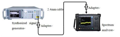
Fig.1 Schematic Diagram of Connection of Signal Generator and Spectrum Analyzer
(b) Reset the spectrum analyzer into the default state: Press [Reset].
(c) Enable the channel power measurement function: Press [Measure], [Channel Power] and [Channel Power Off On]. Thus the channel power measurement function is enabled.
(d) Set the center frequency: Press [Measure], [Channel Power] and [Center Freq] to set the center frequency with number keys. Set the center frequency of the spectrum analyzer as the frequency of the tested signal, i.e. 1GHz.
(e) Set the channel power bandwidth: Press [Measure], [Channel Power] and [Channel BW] and set the channel power bandwidth as 1MHz with number keys.
(f) Set the channel power span: Press [Measure], [Channel Power] and [Span] and set the channel power sweeping bandwidth as 2MHz with number keys.
(g) Set the resolution bandwidth and video bandwidth of the spectrum analyzer: Press [BW] and [RBW Auto Man], and set the resolution bandwidth as 30kHz; Press [BW] and [VBW Auto Man], and set the video bandwidth as 30kHz or less.
h) Enable the average function: Press [BW] and [Average Off On], set the averaging times as 16, and enable the average function. If the channel power measurement function is enabled, the “Auto” mode of the detector will change into the “Sample” mode. Two vertical white lines on the screen indicates the channel power bandwidth, and measurement results are displayed at the bottom of the screen.
