

STB8852 RF Impedance Analyzer

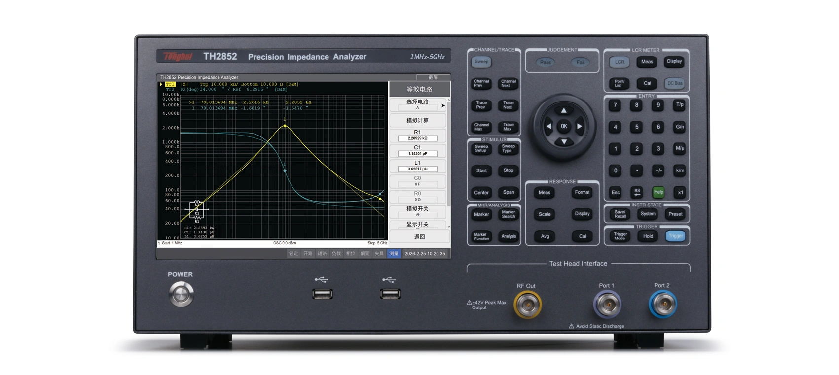
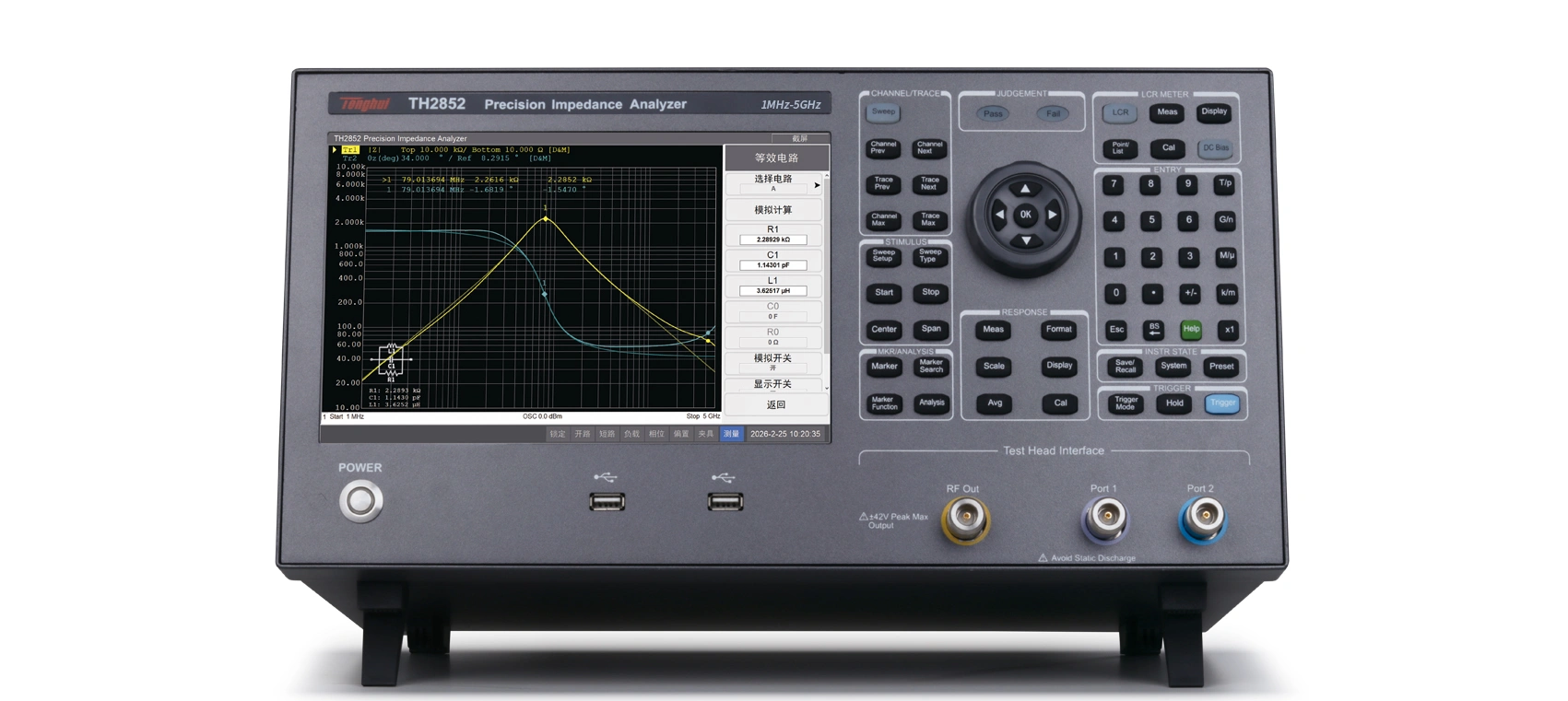
The STB8852 series RF impedance analyzer is a new generation of impedance testing instrument developed using the internationally advanced RF IV method, representing the latest advancement in impedance testing.

The STB8852 series RF impedance analyzer completely surpasses the 3GHz frequency bottleneck of similar instruments; it solves the deficiency of similar instruments that can only analyze and not test independently; its English operating interface, along with both single-test and analysis interfaces, simplifies testing.

A test speed as fast as 0.4ms and an impedance test range of up to 60kΩ can meet the measurement requirements of components and materials, especially beneficial for measuring low-loss (D) capacitors and high-quality factor (Q) inductors. Automatic electrical length measurement and external test terminal configuration effectively eliminate the influence of electromagnetic coupling on the test leads, extending the RF IV impedance testing capability from 3GHz to 5GHz.

Key Features

Test Frequency: 1MHz-5GHz

Basic Accuracy: ±0.3% (typical value)

High Accuracy: Maintains high test accuracy even at GHz levels using the RF IV method.

High Stability and Consistency

High Speed: Test speed up to 0.4ms/point

High Resolution: 10.1-inch capacitive touchscreen, 1280*800 resolution

Point measurement, listing, scanning, equivalent circuit analysis, automated sorting

1601-point multi-parameter list scanning function

Four-parameter measurement

4-channel graphic scanning function, each channel can display 4 curves, with 14 split-screen display modes for channels and curves.

Graphic scanning mode: Individual sorting for each curve, frequency segment scanning and sorting

High Compatibility: Supports SCPI instruction set

Integrated Smith chart allows for RF impedance matching adjustments without a network analyzer.

External test head + automatic electrical balance adjustment

Product Model

STB8852-050

STB8852-100

STB8852-200

STB8852-350

STB8852-500

Display

10.1-inch TFT LCD monitor (1280×RGB×800), capacitive touchscreen

AC measurement parameters

|Z|, |Y|, θ, R, X, G, B, L, C, D, Q, |Γ|, Γx, Γy, θΓ, Vac, Iac, Z (impedance circle), Y (admittance circle), Smith chart, dielectric/magnetic material measurement (optional)

DC measurement parameters

VDC、IDC、RDC

Test frequency

Range:
1MHz – 500MHz

1MHz – 1GHz

1MHz – 2GHz

1MHz – 3.5GHz

1MHz – 5GHz

Maximum Resolution:

1mHz

Test level

AC Voltage: -41dBm – +1dBm

AC Current: 80μA – 10.04 mA

DC bias

Voltage: 0V – ±40V

Current: 0mA – ±100mA

Typical measurement time (speed)

Five Ranges: 0 (Fast) – 5 (Accurate) (Arithmetic average excluding communication time)

0: 0.4ms 1: 4ms 2: 26ms 3: 65ms 4: 130ms 5: 650ms

Maximum Accuracy

±0.3% (Typical)

Measurement Display Range

a 1×10⁻¹⁸; E 1×10¹⁸

Cs, Cp: ±9.99999aF–9.99999EF

Ls, Lp: ±1.00000aH – 99.9999EH

D: ±0.00001 – 9.99999

Q: ±0.01 – 99999.9

R, Rs, Rp, X, Z: ±1.00000aΩ – 999.999EΩ

G, B, Y: ±1.00000aS – 99.9999ES

Vdc: ±1.000000aV – 999.9999EV

Idc: ±1.00000aA – 999.999EA

θr: ±1.00000arad – 3.14159 rad

θd: ±0.0001deg – 180.000deg

Δ%: ±0.0001% – 999.999%

Interface

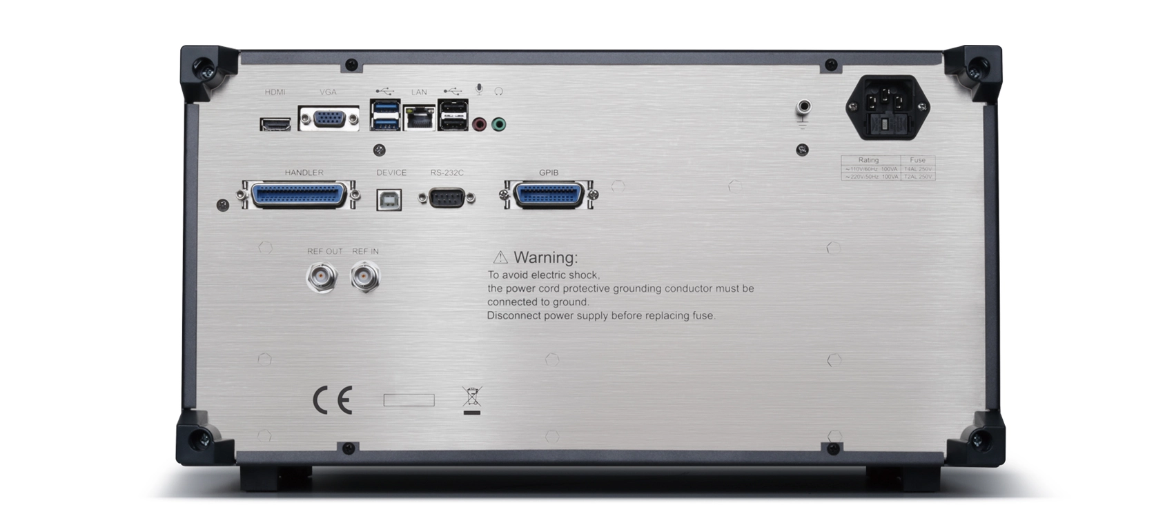
RS232C,USB HOST、USB DEVICE、LAN、GPIB、HANDLER、VGA、HDMI

Warm-up Time:

30 minutes

Input Voltage:

100-120VAC/198-242VAC selectable, 47-63Hz

Power Consumption:

Max 150VA

Dimensions (WxHxD) mm3:

428x220x280

Weight:

14kg

Leave A Message

    Saluki Technology